


PS Engineering
PAV80
Installation and Operator’s Manual
200-800-0101 Appendix B Rev. 5 Feb. 2004
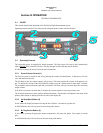
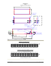
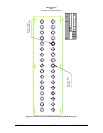
Intercom Jacks (existing)
Video Jack (new)
Typical, 1 each side
13
1211109
4321
Located PVA8021 GLP 7-11-03
12345
14 15161718
6789
19 202122
10
23 24
11 12
25
13
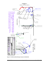
Video Monitor Cable
Video Monitor Cable
PVA802
Distrib. Amp
Video Distribution Cable
Video Cable
3-21-2003
3-20-2003
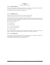
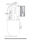
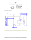
PLAN VIEW
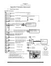
Power to Circuit Breaker
(Note 1)
Antenna Coax
(Note 1)
Power to Circuit Breaker
(Note 1)
Existing
Audio Panel
Audio Wiring to
Audio Panel
(Note 1)
NOTE:
Install wire bundle and cable clamps as required IAW AC43.13-1B:
Section 8, WIRING INSTALLATION INSPECTION REQUIREMENTS
Section 9, ENVIRONMENTAL PROTECTION AND INSPECTION
Section 11, CLAMPING
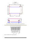
Clean antenna area with solution approved by aircraft manufacturer.
Use 3M Self-adhesive tape (supplied ) to secure antenna to windshield.
Verify that vision is not obscured from any crew position.
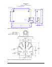
PAV80
Antenna
ELEV VIEW
From Copilot Side
Instrument Panel
FS 59.9
FS 76.5
Top of windshield
-----
Existing
bundle
GLP
NEW RELEASE
CAGE CODE
NONE
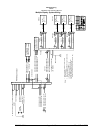
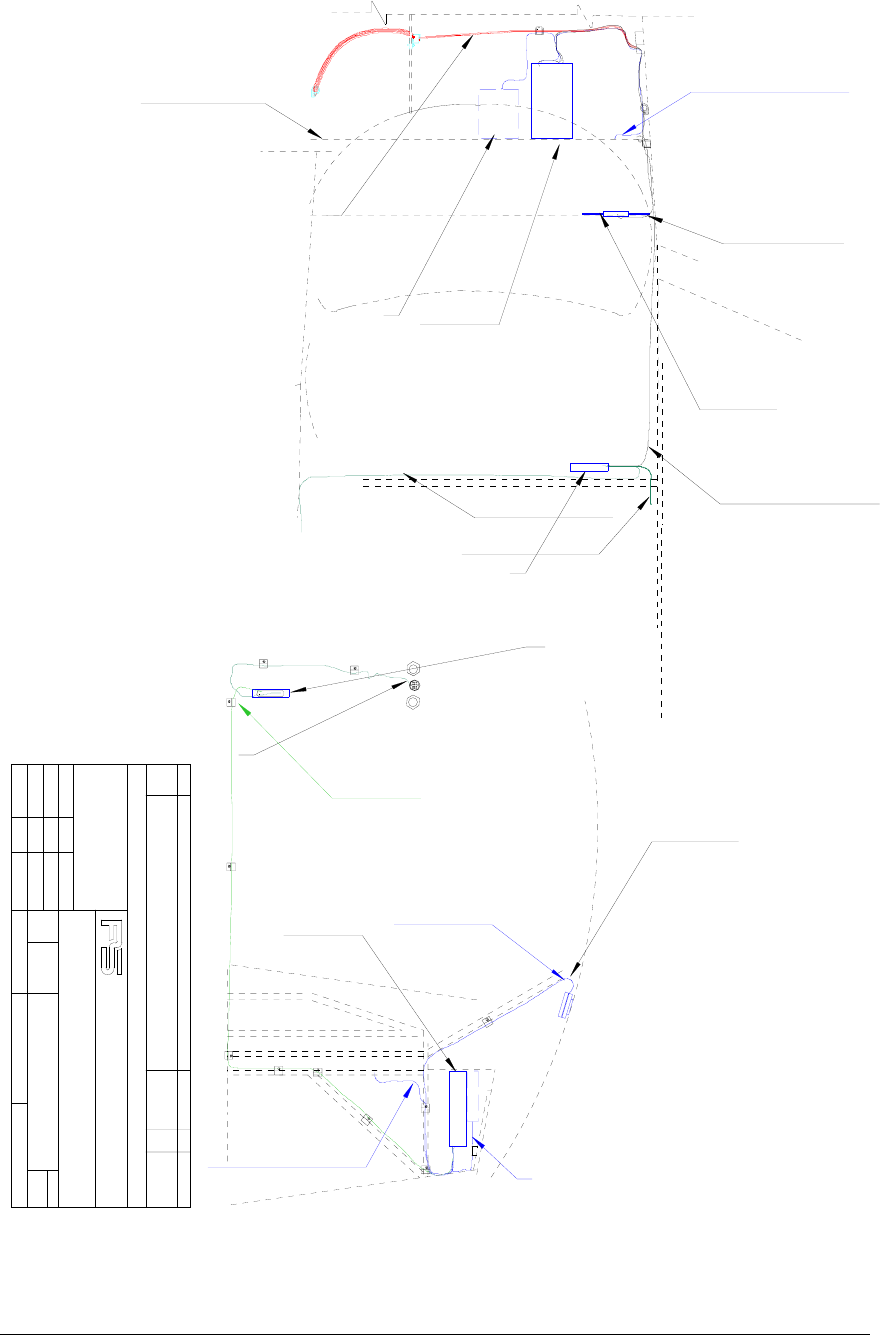
PAV80 Installation Diagram
0
A
CHECKED BY:
APPROVAL:
SCALE
ACTIVITY
DRAWN BY:
NAME
MSS
MATERIAL
REV
DATE
SIZE
TITLE
DESCRIPTION
GLP 3-20-2003
-----
BY
1 OF 1
9800 Martel Road
(865) 988-9800
Lenoir City, Tn 37772
120-800-2488
SHEET
ENGINEERING
INCORPORATED
DRAWING NUMBER
REVISIONS
ECO
1
REV
DATE
H
PAV80
Antenna
Figure 6-2 PAV80 Installation Diagram (Typical) 120-800-2488