


PS Engineering
PAV80 Series IFE System
Installation and Operator’s Manual
200-800-0101 Page ii Rev. 5 Feb. 2004
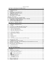
3.5 DISPLAY DIMMING (7)..................................................................................................... 3-5
SECTION IV- WARRANTY AND SERVICE.................................................................. 4-1
4.1 WARRANTY ...................................................................................................................... 4-1
4.2 FACTORY SERVICE .......................................................................................................... 4-1
APPENDIX A – MP3 CREATION ..................................................................................A
5.1 CREATING MP3S FROM AN AUDIO CD..............................................................................A
APPENDIX B – INSTALLATION DRAWINGS.........................................................B
APPENDIX C CONNECTOR INTERCONNECT..............................................................C
7.1 SINGLE DISPLAY SYSTEM...................................................................................................C
APPENDIX D- STC INFORMATION AND INSTRUCTIONS FOR CONTINUING
AIRWORTHINESS ....................................................................................................................D
8.1 INSTRUCTIONS FOR FAA FORM 337, PAV80S..................................................................D
8.2 INSTRUCTIONS FOR CONTINUING AIRWORTHINESS, PAV80S ........................................D
8.3 MASTER DRAWING LIST ....................................................................................................D
APPENDIX E RTCA DO160D/EUROCAE ED-14D ENVIRONMENTAL
QUALIFICATION FORM.........................................................................................................D
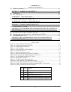
Table of Figures
Figure 2-2 Avionics Mounting Rails (Typical)........................................................................................... 2-2
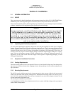
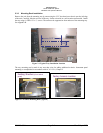
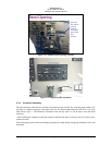
Figure 2-3 Completed panel opening (Typical) .......................................................................................... 2-3
Figure 2-4 Completed panel installation ..................................................................................................... 2-3
Figure 2-5 -Tray Assembly ......................................................................................................................... 2-4
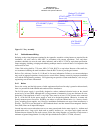
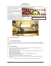
Figure 2-8 View of typical PVA802 Installation ........................................................................................ 2-7
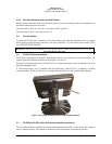
Figure 3-1 Front Panel Controls.................................................................................................................. 3-1
Figure 3-3- Remote Control (not to scale) .................................................................................................. 3-4
Figure 6-1 Panel Location Drawing (Typical) 120-800-8801........................................................................B
Figure 6-2 PAV80 Installation Diagram (Typical) 120-800-2488.................................................................C
Figure 6-3 Tray Installation Drawing, 002-973-0430....................................................................................D
Figure 6-4 Display connector layout.............................................................................................................. E
Figure 6-5 - PVT801 Monitor Dimension Details ......................................................................................... E
Figure 6-6 PVT801 Mounting Tray Dimensions (if used)............................................................................. F
Figure 6-7 Circuit breaker installation drawing 120-800-8802 (typical) .......................................................G
Figure 6-8 PVA802 Video Distribution Amplifier Installation (Dwg. 120-802-0100) .................................H
Figure 6-9 PVA802 Connector viewed from cable side ................................................................................H
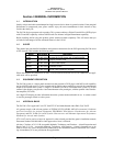
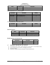
Re
v
Date Change
1 1
st
Release
2 Sept 03 STC Release
3 Nov 03 Remove installation angle restriction
4 Jan 04 Add information on portable display mount
5 Feb 04 Add restriction to use ONLY PS Displays on display power