


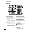
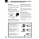

■ System interconnections
1 or 2 Icom 100 W HF transceivers can be connected
as exciters to the IC-PW1. Non-Icom transceivers can
be used, however, band selection will not be synchro-
nized for each exciter.
See the following diagrams for making connections be-
tween the IC-PW1 and an exciter (transceiver). See p.
5 for AC power cable connection.
7
2
INSTALLATION AND CONNECTIONS
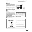
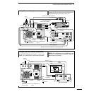
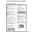
•Using a 13-pin ACC socket (IC-706 series)
IC-PW1
Ground
Coaxial cable
(supplied)
ACC cable (supplied)
Remote control cable (supplied)
To an
antenna
ANT
ACC-1
ANT1
REMOTE
REMOTE
INPUT1
GND
GND
IC-706 series
ACC (13 pins)
OPC-599 (optional)
EXCITER
1 1&2
AC outlet
(Non-Europe versions: 100–120/220–240 V
Europe version : 230 V)
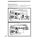
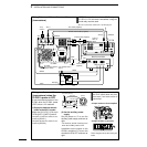
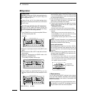
•Using 1 Icom exciter (transceiver)
ANT
ACC-1
ANT2 ANT1 ACC(2) REMOTE
REMOTE
INPUT1
INPUT2
Connect
[INPUT2]
if necessary.
GND
GND
IC-PW1
IC-756
Ground
AC outlet
(Non-Europe versions: 100–120/220–240 V
Europe version : 230 V)
Coaxial cable (supplied)
Coaxial cable
(optional)
ACC cable (supplied)
Be sure to connect the cable
to the 7-pin ACC(2) jack.
Remote control cable (supplied)
To an
antenna
EXCITER
1 1&2