


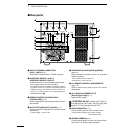
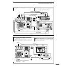
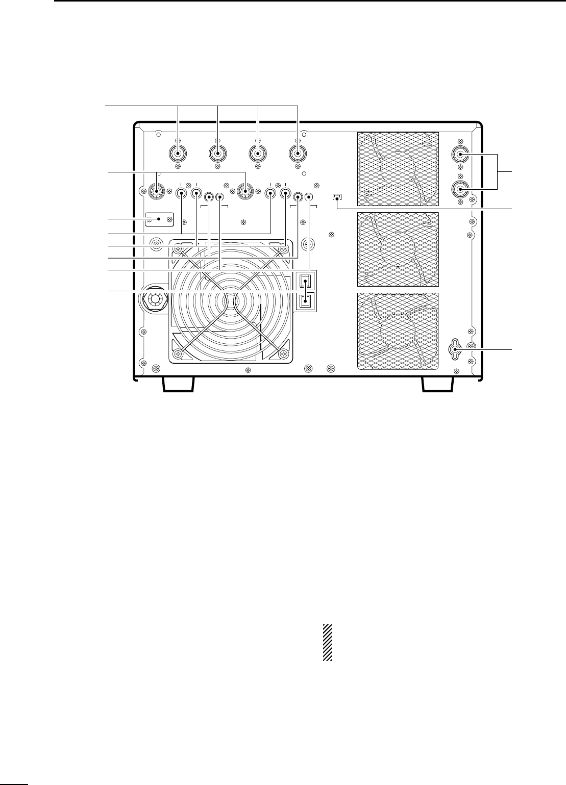
q OUTPUT ANTENNA CONNECTORS
[ANT1] – [ANT4] (p. 6)
Accept a 50 Ω antenna with a PL-259 connector.
w ACCESSORY SOCKET-1 [ACC-1]
ACCESSORY SOCKET-2 [ACC-2]
Enable connection to Icom exciters (transceivers).
- See the page at right for socket information.
- The [ACC-2] socket is connected in parallel with [ACC-1]
by default and can be used for connecting external
equipment such as the EX-627
AUTOMATIC ANTENNA SE-
LECTOR
, etc. These sockets can be separated by the
[EXCITER] switch. (!0)
e REMOTE CONTROLLER CABLE HOLE
[CONTROLLER] (p. 10)
Used for separation of the remote controller and lin-
ear amplifier.
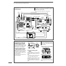
r ALC OUTPUT JACKS [ALC1]/[ALC2] (p. 11)
Connect to the ALC input jack of a non-Icom exciter
(transceiver).
- Control voltage: –10 to 0 V DC
t SEND CONTROL JACKS [SEND1]/[SEND2]
(pgs. 8, 9)
Input terminals for transmit control. Go to ground
while transmitting.
- Max. control level: 5.0 V DC/0.1 A
- Ground level: –0.5 to 0.8 V DC
y CI-V REMOTE CONTROL JACKS [REMOTE]
(pgs. 7–9)
Used for band control with an Icom CI-V exciter
(transceiver).
u ALC LEVEL ADJUSTMENT POTS
[ALC adj1]/[ALC adj2] (p. 11)
Adjust the ALC levels.
RCAUTION! DO NOT operate the IC-PW1 be-
fore adjusting the [ALC adj1] and [ALC adj2] pots
properly. This may damage the final FETs.
i CIRCUIT BEAKERS (p. 14)
Cut off the AC input when over current occurs.
- Circuit breaker capacity: 20 A (U.S.A. version)
15 A (Europe version)
o GROUND TERMINAL (p. 6)
Connect this terminal to a ground to prevent electri-
cal shocks, TVI, BCI and other problems.
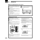
3
1
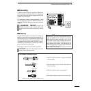
PANEL DESCRIPTION
■ Rear panel
ANT4
ACC-2 ALC2
REMOTE ALC adj2
SEND2 ALC1SEND1
EXCITER
CONTROLLER
ACC-1
ANT3 ANT2 ANT1
INPUT1
INPUT2
1
L
N
1&2
REMOTE ALC adj1
o
!1
!0
e
r
t
u
y
i
q
w