


9
2
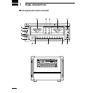
INSTALLATION AND CONNECTIONS
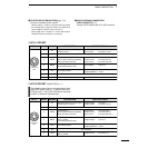
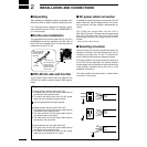
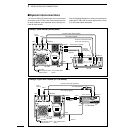
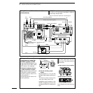
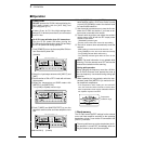
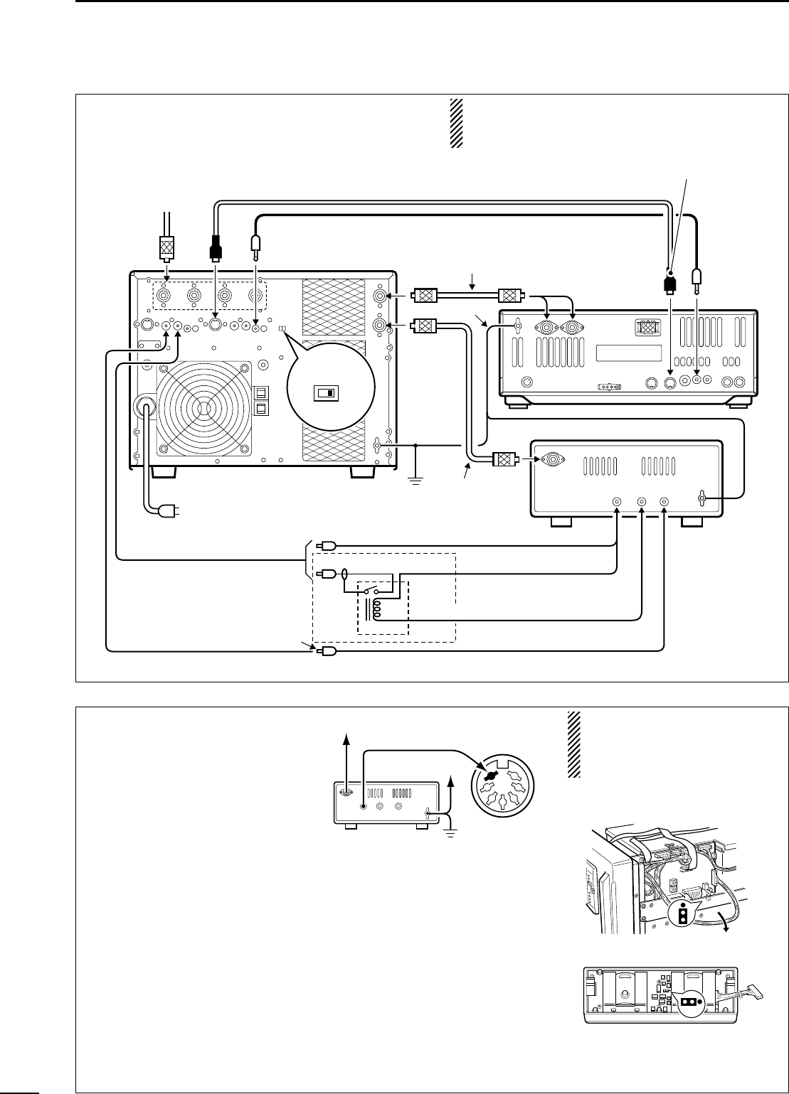
•Using 1 Icom and 1 non-Icom exciters
(transceivers)
NOTE: The specifications for the SEND relay are
5 V DC 0.1 A. If this level is exceeded, a large ex-
ternal relay must be used.
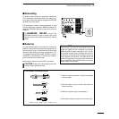
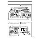
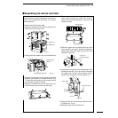
•Using non-Icom exciters
(transceivers) when the
IC-PW1’s power is OFF
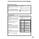
To use the antenna selector of the
IC-PW1 when the IC-PW1 power
is OFF, follow 1 of 2 methods.
(1) Supply the antenna selector
power to the ACC-1 socket
Supply the 13.8 V DC, 0.5 A to pin
7 of the [ACC-1]/[ACC-2] socket.
- Use [ACC-1] when the exciter is con-
nected to [INPUT1].
- Use [ACC-2] when the exciter is con-
nected to [INPUT2].
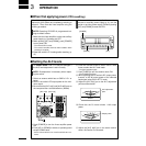
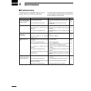
(2) Use the auxiliary power
supply
Set the jumper to ‘2’ to use the
auxiliary power supply as shown at
right.
-The antenna selector functions even
when the IC-PW1 power is OFF
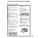
In addition set the jumper on the
IC-PW1 controller to ‘2’ to turn the
controller’s LEDs OFF as shown at
right.
When the jumper is set to ‘2,’
the CI-V control does not func-
tion even if an Icom exciter is
connected.
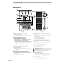
These diagrams show the factory de-
faults.
J3
J4
S3
12
1
2
•Jumper location of linear amplifier
•Jumper location of controller
1
2
3
4
5
6
SEND ALC
RF
DC
GND
[ACC-1]
13.8 V DC
to IC-PW1 [INPUT1]
to IC-PW1 [GND]
IC-PW1 (DIN)
Non-Icom exciter
ANT
ACC-1
ANT
ACC(2) REMOTE
REMOTE
INPUT1
INPUT2
Connect
ANT1 or
ANT2
GND
GND
IC-PW1
IC-756
Ground
Coaxial cable (supplied)
Coaxial cable
(optional)
ACC cable (supplied)
Remote control cable (supplied)
To an
antenna
EXCITER
1 1&2
RCA plug
ALC
ALC2
SEND2
SEND
SEND
Relay
DC power
Non-Icom exciter
GND
RF OUT
ALC
DC OUT
SEND
Be sure to connect the cable to the 7-pin ACC(2) jack.
AC outlet
(Non-Europe versions: 100–120/220–240 V
Europe version : 230 V)