


13
3
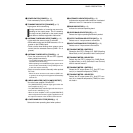
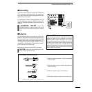
OPERATION
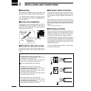
CAUTION:
DO NOT operate the IC-PW1 before adjusting the
ALC levels properly with the [ALC adj1] and
[ALC adj2] pots. (p. 11)
It takes 15 sec. for CI-V line initial settings when
several CI-V devices (more than 5) are connected
to a CI-V line.
For IC-781 users with other Icom CI-V transceivers:
Turn the IC-781 power ON before turning the
IC-PW1 and other transceiver power ON and keep
the IC-781 power ON during operation.
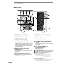
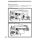
q Push [POWER] to turn the linear amplifier ON then
turn the exciter’s power ON.
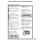
w Select the input/output antenna with [INPUT] and
[ANT].
e Set the exciter to CW or RTTY mode with minimum
output power.
r Select the temperature and SWR meters with
[METER-1] and [METER-2].
- The [TEMP] and [SWR] indicators light.
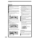
t Push [TUNER] and [AMP/PROTECT] to turn the
automatic antenna tuner and linear amplifier circuit
ON.
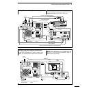
y Push [UP]/[DOWN] to select [AUTO] for automatic
band selection when a CI-V Icom exciter is used;
or push [UP]/[DOWN] to select the desired band
for manual band selection.
u Use the exciter’s antenna tuner to tune the line be-
tween the IC-PW1 and exciter, if you have an an-
tenna tuner connected to the exciter.
i Transmit with the exciter and adjust the exciter’s
output power to 50 W with the RF output power
control on the exciter.
- [TRANSMIT] indicator lights.
- See the exciter’s instruction manual for transmitting.
o The built-in antenna tuner automatically tunes the
antenna.
- SWR reading on meter-2 should be less than 1.2:1.
- Push [TUNER] for 2 sec. to tune the antenna manually.
- The [TUNER] indicator blinks while tuning.
- The [TUNER] indicator lights while the tuner is acti-
vated.
NOTE: The band information is not updated while
scanning. Turn the antenna tuner OFF and use the
manual band selection while scanning.
During split operation:
When changing the frequency more than 100 kHz,
the IC-PW1’s antenna tuner presets the tuner to
the new frequency. Use manual tuning during split
operation.
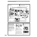
!0 When operating for long periods, select the tem-
perature meter with [METER-1] to monitor the lin-
ear amplifier’s temperature.
- If the temperature meter reading is in the red “HOT”
zone, the exciter should be returned to receive, other-
wise, the protection circuit may be activated and the lin-
ear amplifier may be turned OFF.
DBand memory
The IC-PW1 stores ON/OFF settings for the antenna
tuner and linear amplifier according to the operating
band when at least 1 Icom exciter is connected to the
[INPUT1] connector.
The set conditions may not be stored when the lin-
ear amplifier is turned OFF immediately after set-
ting the antenna tuner and linear amplifier.
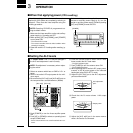
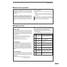
■ Operation
HF/50MHz ALL BAND 1kW LINEAR AMPLIFIER
iPW1
POWER
TRANSMIT
TUNER
DOWN
UP
AUTO
AMP/
PROTECT
1.8 3.5 7 10 14 18 21 24 28 50
TEMP
ID
Po
ALC
SWR
VD
METER-1 METER-2
ANT
INPUT
z
x
z
x
c
v
[POWER]
HF/50MHz ALL BAND 1kW LINEAR AMPLIFIER
iPW1
POWER
TRANSMIT
TUNER
DOWN
UP
AUTO
AMP/
PROTECT
1.8 3.5 7 10 14 18 21 24 28 50
TEMP
ID
Po
ALC
SWR
VD
METER-1 METER-2
ANT
INPUT
z
x
z
x
c
v
HF/50MHz ALL BAND 1kW LINEAR AMPLIFIER
iPW1
POWER
TRANSMIT
TUNER
DOWN
UP
AUTO
AMP/
PROTECT
1.8 3.5 7 10 14 18 21 24 28 50
TEMP
ID
Po
ALC
SWR
VD
METER-1 METER-2
ANT
INPUT
z
x
z
x
c
v
[TUNER][AMP/PROTECT]
METER-1
Temperature
protection range