


5
2
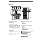
INSTALLATION AND CONNECTIONS
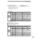
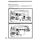
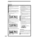
(1) Single-phase 3-wire line (200–240 V AC)
q The green wire from the AC power cable must be
connected to the protective earth.
w The black and white wires from the AC power
cable can be connected to either terminal.
*Use the appropriate AC plug if required.
(2) Single-phase 2-wire line (100–120 V AC)
q The green wire from the AC power cable must be
connected to the protective earth.
w The black wire from the AC power cable must be
connected to the hot (live) wire.
e The white wire from the AC power cable must be
connected to the return wire.
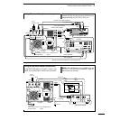
(3) Three-phase 3-wire line (200–240 V AC)
q The green wire from the AC power cable must be
connected to the protective earth.
w The black and white wires from the AC power
cable can be connected to 2 of 3 wires.
white
black
green
*
GND
white
black
green
white
black
green
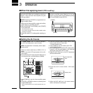
•AC power cable connection (Except Europe version)
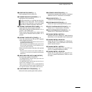
■ Unpacking
After unpacking, immediately report any damage to the
delivering carrier or dealer. Keep the shipping cartons.
For a description and a diagram of accessory equip-
ment included with the IC-PW1, see UNPACKING on
p. ii of this manual.
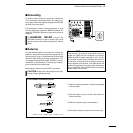
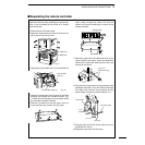
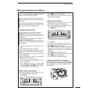
■ Ferrite core installation
The supplied ferrite core and cable clips (o and !0 in
UNPACKING) should be attached to the AC cable of
the IC-PW1 as illustrated below. This will help prevent
interference such as TVI, etc.
■
OPC-853 AC cable with line filter
The IC-PW1 Europe version must be used with the
OPC-853 AC cable to satisfy European EMC require-
ments.
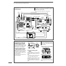
■ AC power cable connection
A suitable AC power plug must be connected to the AC
power cable end. See the diagram below for connec-
tion procedures. AC input voltage is automatically se-
lected.
The IC-PW1 can accept either 100–120 V AC or
200–240 V AC power.* However, we recommend using
200–240 V AC rather than 100–120 V AC for better
power supply efficiency and longer periods of trans-
mission.
*Europe version: 230 V AC only
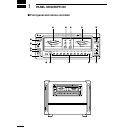
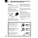
■ Selecting a location
Select a location for the linear amplifier that allows ad-
equate air circulation, free from extreme heat, cold, or
vibrations, and away from TV sets, TV antenna ele-
ments, radios and other electro-magnetic sources.
The linear amplifier and remote controller sections of
the IC-PW1 can be separated. The remote controller
can be placed near the operator for easy monitoring of
linear amplifier conditions at any time. See p. 10 for
separation instructions.
The linear amplifier must be placed on a solid founda-
tion since it is very heavy.
Attach and position
the cable clips to
the AC cable as
illustrated.
AC cable
Ferrite core
Cut the cable clips
so that enough
length remains to
secure the ferrite
core in place.