


10
2
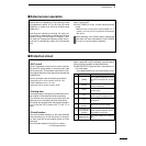
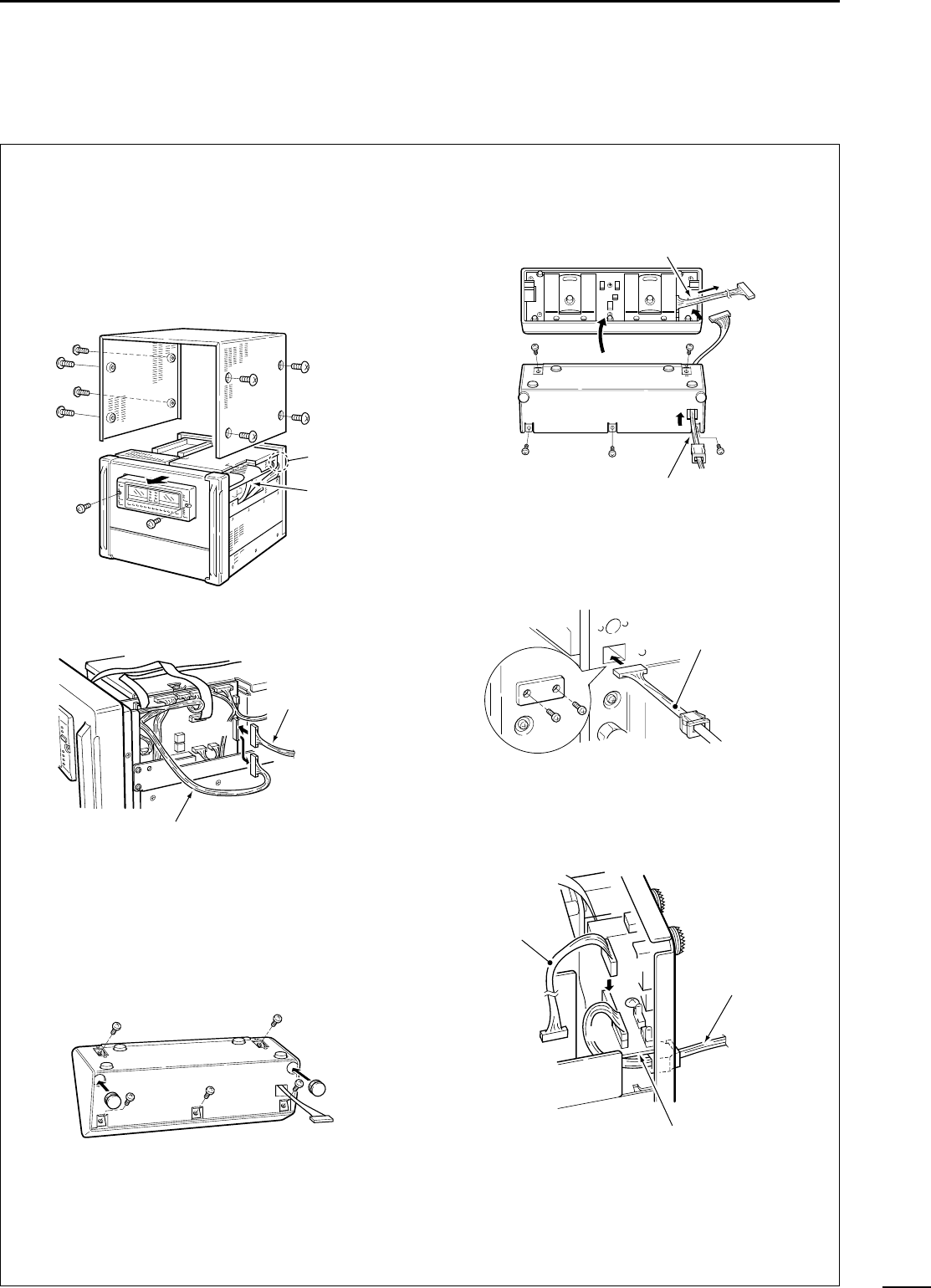
INSTALLATION AND CONNECTIONS
The control section of the linear amplifier can be sep-
arated from the main body, doubling as a remote con-
troller. It can be placed on the exciter or in another
convenient place.
q Disconnect the AC power cable.
w Remove 8 screws from the sides of the linear am-
plifier, then lift up the top cover.
e Unplug the control cable from J3 on the MAIN unit.
r Remove 2 screws from the front panel of the linear
amplifier, then detach the remote controller. (Fig.
1) Attach the dummy panel onto the space left by
the controller using the 2 screws.
t Remove 5 screws from the rear panel of the re-
mote controller, then remove the rear panel.
y Replace the control cable with the supplied sepa-
ration cable through the cable hole. Use the
shorter end (from the bushing) to connect to the
remote controller.
u Remove 2 screws from the cable hole cover on the
linear amplifier rear panel. Insert the separation
cable into the cable hole. Keep the hole cover and
screws for future use.
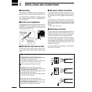
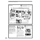
i Plug the other longer end (from the bushing) of the
separation cable into J10 on the JACK unit through
the cable hole. Connect the grounding wire as
shown below. Connect the control cable to J11.
o Plug the other end of the control cable into J3 on
the MAIN unit. (Fig. 2)
!0 Replace the top cover and 8 screws.
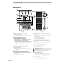
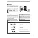
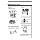
■ Separating the remote controller
Control cable
Separation cable
CONTROLLER
Longer end
(from the bushing)
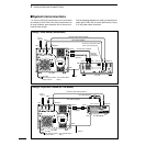
J3
Control cable (step e)
(Fig. 2)
Control cable
(step i)
(Fig. 1)
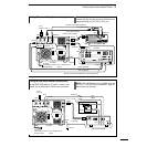
JACK unit
MAIN unit
J11
Control cable
Separation cable
JACK unit
To J3
(MAIN)
J10