


36
|
English
English
|
37
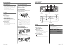
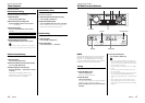
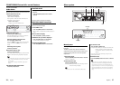
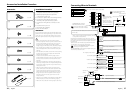
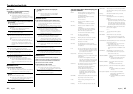
Connecting Wires to Terminals
MUTE
ANT
CONT
P.CONT
FRONT L
FRONT R
REAR L
REAR R
–
+
AUX IN
REAR
SUB
WOOFER
FRONT
FM/AM antenna input
Fuse (10A)
Wiring harness
(Accessory1)
Ignition wire (Red)
Battery wire (Yellow)
Ground wire (Black) - (To car chassis)
Ignition key
switch
Car fuse box
(Main fuse)
ACC
Car fuse
box
Battery
If no connections are made, do not let the wire come out
from the tab.
Dimmer control wire (Orange / White)
To car light control switch
External amplifier control wire
(Pink / Black)
To "EXT.AMP.CONT." terminal of the amplifier having the
external amp control function.
To front left speaker
To front right speaker
To rear left speaker
To rear right speaker
White/Black
White
Gray/Black
Gray
Green/Black
Green
Purple/Black
Purple
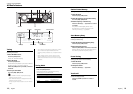
To KENWOOD disc changer/
External optional accessory
To connect these leads, refer to
the relevant instruction manuals.
Power control wire (Blue/White)
When using the optional power amplifier, connect
to its power control terminal.
Motor antenna control wire (Blue)
To connect the KENWOOD navigation system,
consult your navigation manual.
TEL mute wire (Brown)
Connect to the terminal that is grounded when either
the telephone rings or during conversation.
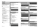
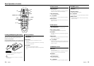
A
B
C
Ez900HDS/Ez700SR
A Aux input
B Rear output
C Front output
D Subwoofer output
Depending on what antenna you are using, connect
either to the control terminal of the motor antenna, or to
the power terminal for the booster amplifier of the film-
type antenna.
D
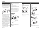
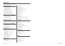
Accessories/ Installation Procedure
Installation Procedure
1. To prevent a short circuit, remove the key from
the ignition and disconnect the - battery.
2. Make the proper input and output wire
connections for each unit.
3. Connect the speaker wires of the wiring harness.
4. Connect the wiring harness wires in the
following order: ground, battery, ignition.
5. Connect the wiring harness connector to the
unit.
6. Install the unit in your car.
7. Reconnect the - battery.
8. Press the reset button.
2WARNING
If you connect the ignition wire (red) and the battery wire
(yellow) to the car chassis (ground), you may cause a short
circuit, that in turn may start a fire. Always connect those
wires to the power source running through the fuse box.
• If your car’s ignition does not have an ACC position,
connect the ignition wires to a power source that can be
turned on and off with the ignition key. If you connect
the ignition wire to a power source with a constant
voltage supply, as with battery wires, the battery may die.
• If the console has a lid, make sure to install the unit so
that the faceplate will not hit the lid when closing and
opening.
• If the fuse blows, first make sure the wires aren’t touching
to cause a short circuit, then replace the old fuse with
one with the same rating.
• Insulate unconnected wires with vinyl tape or other
similar material. To prevent a short circuit, do not remove
the caps on the ends of the unconnected wires or the
terminals.
• Connect the speaker wires correctly to the terminals to
which they correspond. The unit may be damaged or fail
to work if you share the - wires or ground them to any
metal part in the car.
• When only two speakers are being connected to the
system, connect the connectors either to both the front
output terminals or to both the rear output terminals
(do not mix front and rear). For example, if you connect
the + connector of the left speaker to a front output
terminal, do not connect the - connector to a rear
output terminal.
• After the unit is installed, check whether the brake lamps,
blinkers, wipers, etc. on the car are working properly.
• Mount the unit so that the mounting angle is 30° or less.
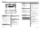
Left output (White), Right output (Red)
Sirius antenna
(Accessory8)
• Connection part is
fixed on vinyl tape so
that Sirius antenna is
does not come out.
• Do not bend Sirius
antenna input code
strongly.
Sirius antenna input
See next page for Mounting
the SIRIUS Antenna.
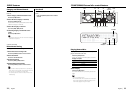
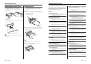
Accessories
1
..........1
2
..........2
3
..........4
4
..........4
5
..........1
6
..........1
7
..........2
8
..........1
1
2
3