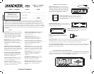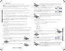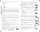
KEYPAD
Here is a brief description of the soft touch
buttons.
- Used to select memory preset 1
or to store current settings into
memory preset 1.
- Used to select memory preset
2 or to store current settings into
memory preset 2.
- Used to select memory preset
3 or to store current settings into
memory preset 3.
- Used to select memory preset
4 or to store current settings into
memory preset 4.
- Used to exit the current menu.
- Used to enter the selected
menu.
- Used to return to the Main
Menu and other functions explained
later in this manual.
- Used to advance up through
menu selections and/or adjust WXRC
and amplifier controls.
- Used to advance down
through menu selections and/or adjust
WXRC and amplifier controls.
4
MOUNTING
WXRCREMOTECONTROL
5
MOUNTING
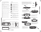
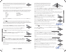
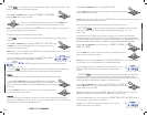
Vacuum Flourescent Display (VFD)
Here is a brief description of the indicators
found on the VFD:
- Indicates the WXRC and/or WX
Series amplifier controls are locked out and
not usable.
- Indicates you are in the System Menu
- Indicates you are in the mute menu
or the mute function is active.
- Indicates you are in the gain menu.
- Indicates you are in the equalizer menu.
- Indicates you are in the low pass filter
menu.
- Indicates you are in the high pass filter
menu.
- Indicates you are in the phase
menu.
- Indicates you are in the LIMITER
menu.
- Memory preset 1 activated or
stored.
- Memory preset 2 activated or
stored.
- Memory preset 3 activated or
stored.
- Memory preset 4 activated or
stored.
These controls and their usage will be explained later with more detail in each menu usage section
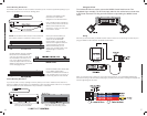
Mounting
DIN Mounting
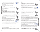
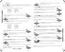
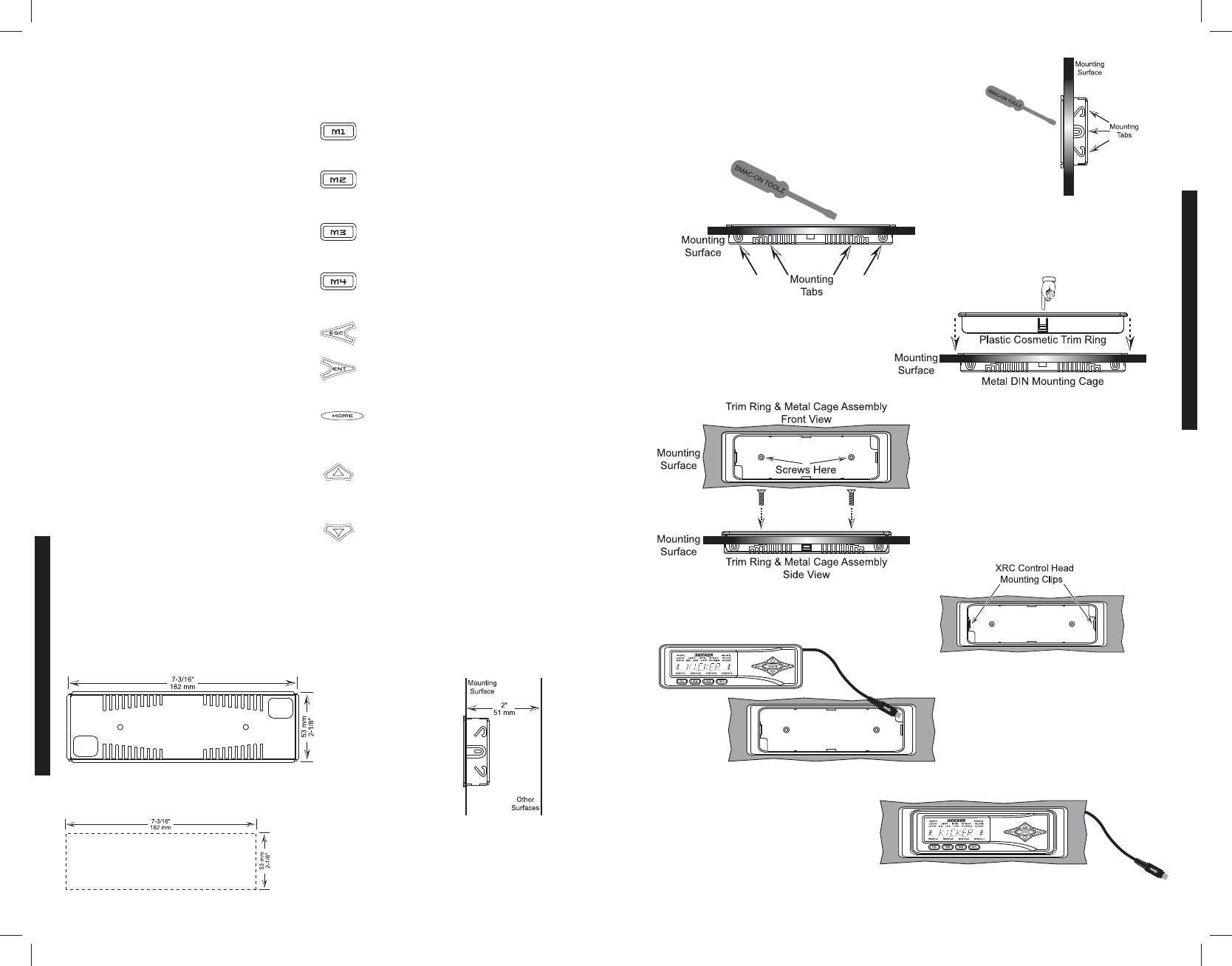
Using the supplied hardware you can mount the WXRC into a standard DIN sized opening.
Be sure you will have
a minimum of 2” (51
mm) clearance depth
behind your mounting
surface panel to
mount the WXRC.
If not using an existing DIN opening, you will first need to cut an opening that
is 7-3/16” (182 mm) by 2-1/8” (53 mm) into your mounting surface panel.
It is VERY important that you DO NOT make the hole any
larger than the specified dimensions. If you make the
opening too large then the mounting cage will not work
properly.
Side View
Top and Bottom View
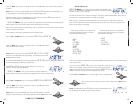
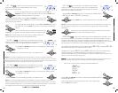
Using the existing DIN opening or the one you just created,
slide the Metal DIN Mounting Cage into the opening.
Secure the Cage by bending the Mounting Tabs on the
sides, top and bottom of the Cage using a small flat-blade
screwdriver. Use only the tabs that when bent will secure
the Cage to the Mounting Surface.
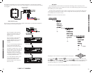
Next, place the Plastic Cosmetic Trim
Ring into the Metal DIN Mounting cage.
There are two plastic retainers in the Trim
Ring (one on top and one on bottom)
that will snap into place.
Once in place, use the 2 supplied M3
flathead screws to secure the Trim
Ring to the Metal Cage.
The WXRC Control Head is held in
place by two clips (one on each side)
of the Plastic Trim Ring.
Route the WXRC Control Head cable
through one of the openings in the Trim
Ring/Metal Cage assembly to your
WXRC Interface Box location.
W
Press the WXRC control head in to
the assembly until it locks into place.
Your WXRC Control Head is now
mounted and you can move on to
the wiring section of this manual


