


37
Advanced Operations
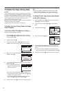
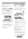
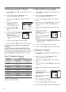
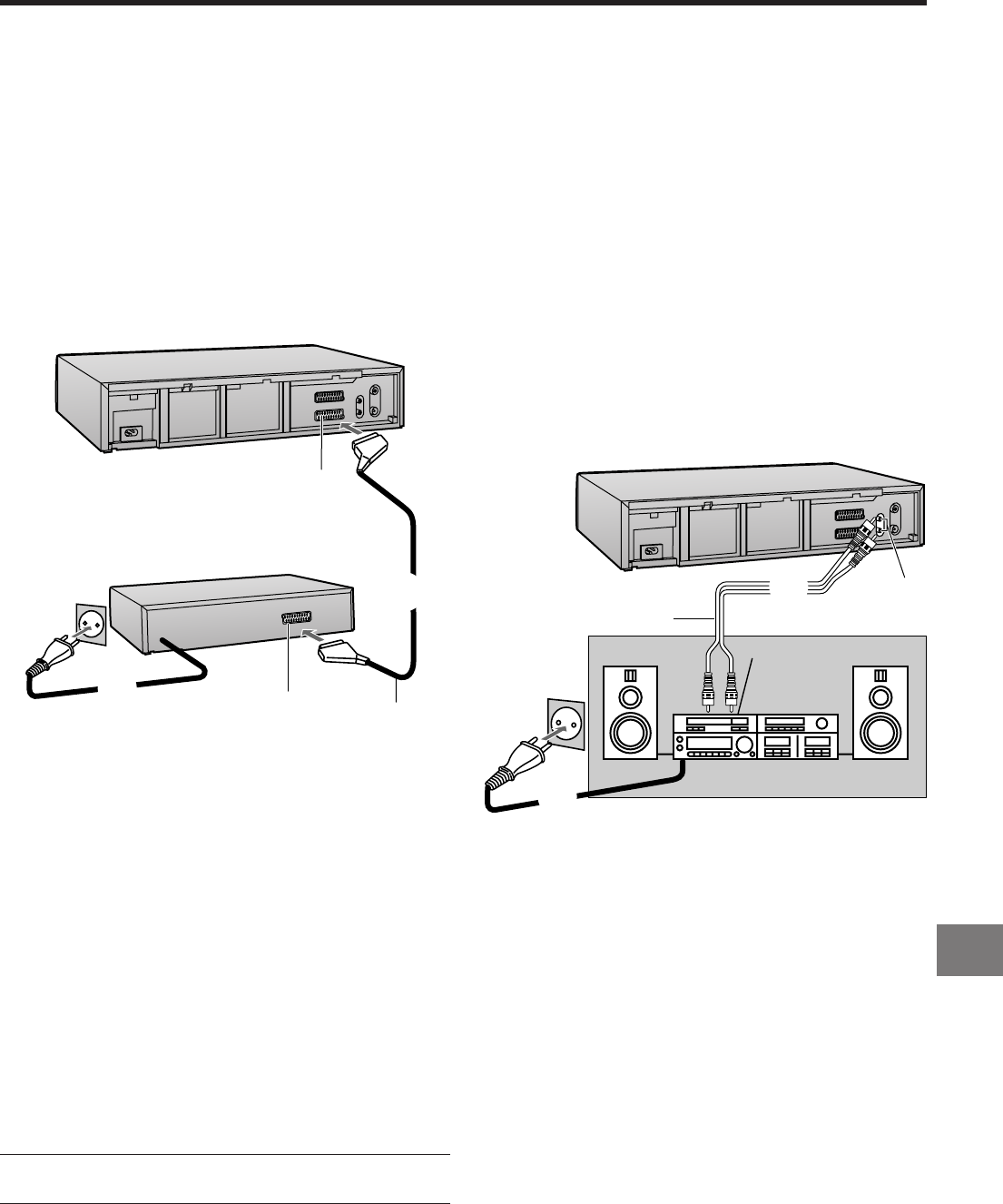
1 Connect a 21-pin Scart cable (not supplied) to the AV2
21-pin Scart socket g on the VCR and to the 21-pin
Scart socket on the decoder.
2 Connect the decoder’s mains lead to an AC mains
socket.
3 Set “AV2” to “DECODER”.
For details, see page 50.
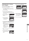
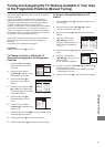
AV Link Function
If the VCR is connected to the TV via a 21-pin Scart cable,
you can use the AV LINK button B to switch the TV from
normal TV reception over to the video playback channel (AV
input) (and vice versa). In the VCR mode (when the VCR
indication in the VCR display is lit), the TV is switched to the
video playback channel (AV input). In the TV mode (when the
VCR indication is not lit), the TV is switched to TV reception.
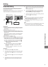
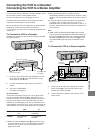
Connecting the VCR to a Decoder/
Connecting the VCR to a Stereo Amplifier
To connect this VCR to a decoder or a stereo amplifier, make
the connections shown in the illustration below.
For the connection to the TV, see pages 10 and 12.
For details about the connection, also read the operating
instructions of the decoder or stereo amplifier.
Be sure to keep the VCR, TV and decoder or stereo amplifier
switched off until you have finished all connections.
For your safety, do not connect or handle the equipment with
wet hands.
To Connect the VCR to a Decoder
Decoder here refers to the device used to decode scrambled
broadcasts (Pay TV).
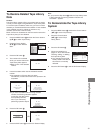
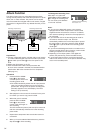
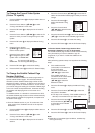
1 Connect an Audio cable (not supplied) to the Audio
Output sockets h on the VCR and to Audio Input
sockets on the stereo amplifier.
2 Connect the stereo amplifier’s mains lead to an AC
mains socket.
≥ When you start playback on the VCR, the TV is
automatically switched to the VCR mode. However, during
playback, it is not possible to switch the TV back to the TV
mode.
≥ If a Pay TV station has been selected on the VCR when
you switch to the TV mode, the picture on the TV is
scrambled when you select a Pay TV station on the TV. In
this case, either switch to the VCR mode or select the AV
input on the TV.
Hint:
≥ “RGB” means separate Red/Green/Blue colour signals.
If you connect a TV equipped with RGB input capability to
the AV1 socket f on this VCR, and a decoder equipped
with RGB output capability to the AV2 socket g, the TV
can receive RGB signal input from the decoder via the
VCR.
To Connect the VCR to a Stereo Amplifier
2
1
h
Stereo amplifier (not supplied)
To an AC mains socket
Audio Input sockets
Audio cable
(not supplied)
2
1
g
Decoder (not supplied)
To an AC mains socket
21-pin Scart socket
21-pin Scart cable
(not supplied)
≥ When you press the MENU button U to display the menu
on the TV screen, the TV is also automatically switched to
the VCR mode, however, the VCR indication does not
appear in this case.
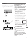
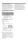
VCR Mode
TV Mode
VCR
VCR indication
is lit.
VCR indication
is not lit.
TV
AV Input
is selected.
TV reception is
selected.