


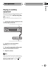
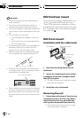
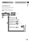
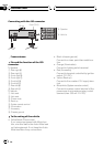

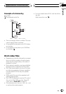

Connecting with the ISO connector
A
B
To Speaker
To Vehicle
1
357
2
468
1
357
2
468
Fuse (10 A)
15 cm
From antenna
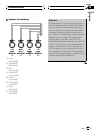
Pin and the function of the ISO
connector
To Speaker
1 Rear right +
2 Rear right *
3 Front right +
4 Front right *
5 Front left +
6 Front left *
7 Rear left +
8 Rear left *
To Vehicle
1 Not used.
2 Not used.
3 Phone mute
4 Back up
5 System remote control
6 Illumination
7 Accessory
8 Chassis ground
To the wiring of the vehicle
! Yellow/black (Phone mute)
If you use an equipment with Mute func-
tion, wire this lead to the Audio Mute lead
on that equipment. If not, keep the Audio
Mute lead free of any connections.
! Black (chassis ground)
Connect to a clean, paint-free metal loca-
tion.
! Orange (Illumination)
Connect to lighting switch terminal.
! Red (Accessory)
Connect to terminal controlled by ignition
switch (12 V DC).
! Yellow (Back up)
Connect to the constant 12 V supply term-
inal.
! Blue/white (System remote control)
Connect to system control terminal of the
power amp or auto-antenna relay control
terminal (max. 300 mA 12 V DC).
Connection
En
44
Section
14