


WARNING
! Use speakers over50 W (outputvalue) and be-
tween 4 Wto 8 W(impedance value). Donot
use 1 Wto 3 Wspeakers for thisunit.
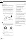
! The black cableis ground. Wheninstalling
this unit orpower amp (soldseparately), make
sure to connectthe ground wirefirst. Ensure
that the groundwire is properlyconnected to
metal parts ofthe car’s body. Theground wire
of the poweramp and theone of this unitor
any other devicemust be connectedto the car
separately withdifferent screws. If thescrew
for the groundwire loosens or fallsout, it
could result infire, generation ofsmoke or
malfunction.
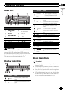
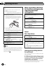
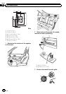
Ground wire
Metal parts of car’s body
Other devices
(Another electronic
device in the car)
POWER AMP
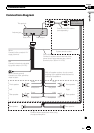
Important
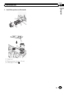
! When installingthis unit in avehicle without
an ACC (accessory) positionon the ignition
switch, failureto connect the redcable to the
terminal that detectsoperation of theignition
key may resultin battery drain.
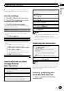
O
N
S
T
A
R
T
O
F
F
ACC position No ACCposition
! Use this unitwith a 12-voltbattery andnega-
tive grounding only. Failure todo so mayresult
in a fireor malfunction.
! To preventa short-circuit, overheating or mal-
function, besure to followthe directions
below.
— Disconnect the negativeterminal of the
battery before installation.
— Secure thewiring with cable clampsor ad-
hesive tape.Wrap adhesive tapearound
wiring that comesinto contact withmetal
parts to protectthe wiring.
— Place all cablesaway from movingparts,
such as thegear shift andseat rails.
— Place all cablesaway from hotplaces,
such as nearthe heater outlet.
— Do not connectthe yellow cableto the bat-
tery by passing itthrough the holeto the
engine compartment.
— Cover any disconnected cable connectors
with insulating tape.
— Do not shortenany cables.
— Never cutthe insulation of thepower cable
of this unitin order to sharethe power
with other devices. The currentcapacity of
the cable islimited.
— Use a fuseof the ratingprescribed.
— Never wire thenegative speaker cabledi-
rectly to ground.
— Never bandtogether negative cablesof
multiple speakers.
! When this unitis on, control signalsare sent
through theblue/white cable. Connectthis
cable to thesystem remote controlof an exter-
nal power ampor the vehicle’s auto-antenna
relay control terminal(max. 300 mA12 V DC).
If the vehicleis equipped witha glass anten-
na, connectit to the antennabooster power
supply terminal.
! Never connectthe blue/white cableto the
power terminalof an external poweramp.
Also, neverconnect it tothe power terminal of
the auto antenna.Doing so mayresult in bat-
tery drain or amalfunction.
En
10
Section
02
Connections