


Connecting your equipment
03
19
En
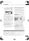
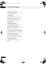
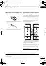
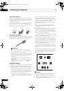
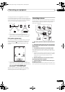
3 If the device can output digital audio, connect an
optical-type
1
digital audio output from the recorder to
the
OPTICAL IN 2
(
DVR1
) input.
Use an optical cable for the connection.
2
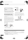
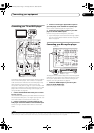
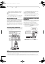
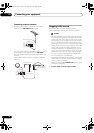
Using the component video jacks
Component video should give superior picture quality
when compared to composite or S-Video. You can also
take advantage of progressive scan video (if your source
and TV are both compatible), which delivers a very stable,
flicker-free picture. See the manuals that came with your
TV and source component to check whether they are
compatible with progressive-scan video.
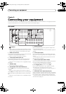
1 Connect the component video outputs of your
source to a set of
ASSIGNABLE COMPONENT VIDEO
inputs.
Connect using a three-way component video cable.
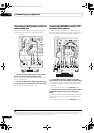
• Since they are assignable, it doesn’t matter which
component video inputs you use for which source.
After connecting everything, you’ll need to assign the
component video inputs—see The Input Setup menu
on page 69.
2 Connect the
COMPONENT VIDEO MONITOR OUT
jacks to the component video inputs on your TV or
monitor.
Use a three-way component video cable.
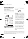
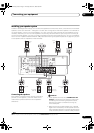
Connecting digital audio sources
This receiver has both digital inputs and outputs,
allowing you to connect digital audio components for
playback and for making digital recordings.
Most digital components also have analog connections.
See Connecting analog audio sources on page 20 if you
want to connect these too.
Note
1 • In order to record, you must connect the analog audio cables (the digital connection is for playback only).
• If your video component doesn’t have a digital audio output, you can skip this step.
2 If your recorder only has a coaxial digital output, you can connect it to one of the coaxial inputs on this receiver using a coaxial digital audio cable. When
you set up the receiver you’ll need to tell the receiver which input you connected the recorder to (see also The Input Setup menu on page 69).
T
I CH IN
SPEAKERS
B
A
CD CD-R
ANTENNA
PRE OUT
DVR1
IN IN IN
Y
INOUT
OUT
DVR2 ZONE 2
IN
INOUT
MONITOR
OUT
MONITOR
OUT
FM UNBAL 75
COMPONENT VIDEO
OUT
OUT
OUT OUT
FRONT CENTER
FRONT CENTER SURROUND SURROUND BACK /
RLRLRL
(Single)
SURROUND
SURROUND BACK
SUBWOOFER
SURROUNDSURROUND BACK
(Single)
1
IN
2
IN
3
IN
ASSIGNABLE
31-
AM LOOP
IN
SIRIUS
P
B
P
R
SELECTABLE SEE INSTRUCTION MANUAL
SELECTABLE VOIR LE MODE D'EMPLOI
Y
MONITOR
OUT
COMPONENT VIDEO
1
IN
P
B
P
R
Y
P
B
P
R
COMPONENT
VIDEO
Y
P
B
P
R
COMPONENT
VIDEO
2
1
VSX-01TXH
TV
DVD player
DIGITAL
ASSIGNABLE
ASSIGN-
ABLE
OPTICAL
RS-232C
MULTI CH IN
SPEAKERS
A
DVD TV SAT DVR1
CON-
TROL
IR
ZONE2
COAXIAL
HDMI
OUT
OUT
BD IN
21-
ASSIGNABLE
21-
21-
2
IN
(DVR1)
1
IN
1
IN
2
IN
(TV SAT)
1
IN
S-
VIDEO
AUDIO
L
R
L
R
IN
IN
IN IN
IN
INOUT
OUT
DVR2
IN
INOUT
M
O
OUT
FRONT
F
R
CENTER
SURROUND
SURROUND BACK
SUBWOOFER
VIDEO
(DVD)
2
IN
(CD)
OUT
OUT
IN
IN
S
XM
IN
1
2
12 V TRIGGER
(
OUTPUT
12 V TOTAL
50 mA MAX
)
OUT
2
IN
(CD)
2
IN
(DVR1)
OPTICAL
COAXIAL
OPTICAL
DIGITAL IN
OPTICAL COAXIAL
DIGITAL OUT
12
VSX-01TXH
CD-R, MD,
DAT, etc.
VSX-01TXH_KU.book Page 19 Thursday, March 27, 2008 9:00 PM