


4 © 2011 Polk Audio—all rights reserved © 2011 Polk Audio—all rights reserved 5
TOOLS OF THE TRADE
Listed next are the majority of the tools required to perform an installation.
Having the proper tools will make the installation that much easier.
• Phillipsheadscrewdriver •Solderless,crimp-onconnectorsandacrimpingtool
• Electricdrilland3/16"and1/8"drillbits •Safetyglasses
• Permanentinkmarkerorpencil •DMMorVOM
• Safetyglasses •Nylontiestraps
• Wirestrippersandcutters •Wirecrimper
• Electricaltape •Grommetsforpassingwiresthroughmetalcarwalls
• AmplifierPowerWire
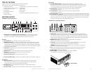
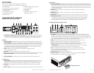
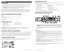
END PANEL LAYOUTS
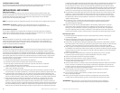
PA D5000.5 Line Level Inputs/Controls
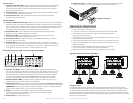
1. Status LEDs (on top of amplifier): Power and Protection—Power will illuminate to indicate
the amplifier is on and operating normally; Protection will illuminate if the amplifier shuts down
due to short circuit, DC offset, or overheating detected by onboard protection circuitry.
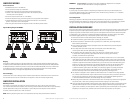
Subwoofer
2. Sub 1/Sub2 Inputs—Line level inputs for subwoofer signal from head unit
3. SUB/INT Source Switch—Set the switch to the SUB position if you are connecting your head unit’s
subwooferoutputtotheSUB1orSUB2inputs.SettheswitchtotheINTpositionifyouaresending
a full range signal to the full range inputs (FL, FR, RL, RR) and not connecting anything to the SUB inputs.
IntheINTposition,theamplifierwillfilterthebassfrequenciesfromthefullrangesignalandsendthem
to the subwoofer amplifier channel.
4. Level Control—Adjusts the gain of the subwoofer amplifier channel to match the output
voltage from your head unit.
5. SUB Sonic Filter—Attenuates the frequencies below the settings on the control.
6. LPF Control—Adjusts the low pass filter frequency to attenuate frequencies
above the setting on the control.
7. Remote Level Control Jack—Connects remote bass level control.
8. Line Level Front/Rear Inputs—Accepts line level input from the front and rear channels of a head unit.
Rear Controls
9. Rear Full, HPF Switch—Selects between no filtering or a high pass filter. The FULL setting
does not attenuate any frequencies and is for full-range speaker systems. The HPF attenuates
low frequencies and is used with mid-range speakers and tweeters.
10. Rear HPF Control—Adjusts the high pass filter frequency to attenuate frequencies below
the setting on the control.
11. Rear Level Control—Adjusts the gain of the rear channels to match the output voltage from your head unit.
L
R
L
INPUT OUTPUT
R
LPF
LPF
HPF LEVEL
BPF
FULL
HPF
X-OVER
HPF
X-OVER
FREQ x 10
FREQ x 1
FREQ x 10
FREQ x 1
20Hz400Hz 6V 200mV50Hz 500Hz
GND
12VREM
25A25A
LLRR
BRIDGED
L
R
L
R
LPFHPF LEVELLPFHPFLEVEL
HPF
BPF
FULL
HPF
BPF
FULL
ST
4CH
FRONT
REAR
X-OVER
X-OVER
FREQ x 10
FREQ x 1
FREQ x 10
FREQ x 1
50Hz 500Hz 50Hz 500Hz20Hz 400Hz 20Hz 400Hz6V 200mV 6V 200mV
CHANNEL
MODE
GND
12VREM
40A
35A
RL FL
RR
REAR
FRONT
FR
RR FR
RL FL
INPUT
SUB 1
SUB 2
SOURCE
SUB
INT
LEVEL
SUB
SONIC
LPF
REMOTE LEVEL CONTROL
INPUT
FR RR
FL RL
4CHST
CHANNEL
MODE
LPFHPF LEVEL
BPF
FULL
HPF
HPFFULL
HPF LEVEL
FRONT
REAR
6V 200mV
6V 200mV
20Hz 38Hz 40Hz 220Hz
40Hz 4000Hz 6V 200mV40Hz 400Hz80Hz4000Hz
SUB
GND
12VREM
40A40A
RL FL
SUB
RR FR
RR FR
SUB
RL FL
2876543
PA D1000.1
1432 5
27654b4a3a
PA D2000.2
3b 1432 5
21211
PA D4000.4
4a 5a 9a 10a
4b 5b 9b 10b6 7 8
14323
8
5
2
1
PA D5000.5
109 11 15 1612 13 14
1432
1
1
1
3 4 6 75
5
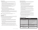
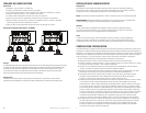
Front Controls
12. Front FULL, HPF, BPF Switch—Selects full range, high pass filter, or band-pass filter. The
FULL setting does not attenuate any frequencies and is for full range speaker systems. The HPF setting
attenuates low frequencies and is used with mid-range speakers and tweeters. The BPF setting allows
you to use both the high pass filter and low pass filter, and is used with mid-range drivers.
13. Front LPF Control—Adjusts the low pass filter frequency to attenuate frequencies
above the setting on the control.
14. Front HPF Control—Adjusts the high pass filter frequency to attenuate frequencies
below the setting on the control.
15. Front Level Control— Adjusts the gain of the front channels to match the output voltage from your head unit.
16. Channel Mode Switch (4CH/ST)—Set the switch to 4CH if you are using four channel outputs from your head
unit to the FL, FR, RL, RR inputs on the amplifier. Set the switch to ST (stereo) mode if you are using two channel
outputs from your head unit. In the ST position, the amplifier will take the signal input to the FL and FR inputs
and send the same signals also to the RL and RR amplifier channels.
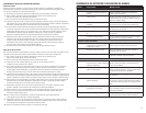
PA D5000.5 Power Inputs/Speaker Outputs
1. GND (Ground)—Connect this terminal directly to the metal chassis of the vehicle, using the shortest
wirenecessarytomakethisconnection.Alwaysusewireofthesamegaugeorlargerthanthe+12Vpower
wire. The chassis connection point should be scraped free of paint and dirt. Use only quality crimped and/or
soldered connectors at both ends of this wire. DO NOT connect this terminal directly to the vehicle battery
ground terminal or any other factory ground points.
2. REM (Remote Turn On)—Thisterminalturnsontheamplifierwhen+12Visappliedtoit.
Connect it to the remote turn on lead of the head unit.
3. +12V Power—Connect this terminal through a FUSE or CIRCUIT BREAKER to the positive terminal
of the vehicle battery or the positive terminal of an isolated audio system battery.
WARNING: Always protect this power wire by installing a fuse or circuit breaker of the appropriate
sizewithin12"ofthebatteryterminalconnection.
4. Fuse—These fuses (40A x 2) protect the amplifier against internal electrical damage and are meant
to protect only the amplifier. All other power connections should be fused at the power source.
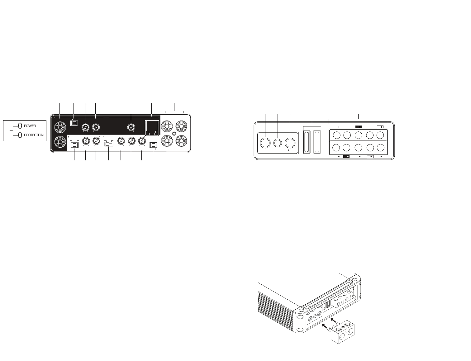
5. Speaker Output—Connect the speakers here.
6. Terminal Adaptor—The adaptor enables the use of cable up to 0000AWG
forthegroundand+12Vconnections(seeillustrationbelow).
L
R
L
INPUT OUTPUT
R
LPF
LPF
HPF LEVEL
BPF
FULL
HPF
X-OVER
HPF
X-OVER
FREQ x 10
FREQ x 1
FREQ x 10
FREQ x 1
20Hz400Hz 6V 200mV50Hz 500Hz
GND
12VREM
25A25A
LLRR
BRIDGED
L
R
L
R
LPFHPF LEVELLPFHPFLEVEL
HPF
BPF
FULL
HPF
BPF
FULL
ST
4CH
FRONT
REAR
X-OVER
X-OVER
FREQ x 10
FREQ x 1
FREQ x 10
FREQ x 1
50Hz 500Hz 50Hz 500Hz20Hz 400Hz 20Hz 400Hz6V 200mV 6V 200mV
CHANNEL
MODE
GND
12VREM
40A
35A
RL FL
RR
REAR
FRONT
FR
RR FR
RL FL
INPUT
SUB 1
SUB 2
SOURCE
SUB
INT
LEVEL
SUB
SONIC
LPF
REMOTE LEVEL CONTROL
INPUT
FR RR
FL RL
4CHST
CHANNEL
MODE
LPFHPF LEVEL
BPF
FULL
HPF
HPFFULL
HPF LEVEL
FRONT
REAR
6V 200mV
6V 200mV
20Hz 38Hz 40Hz 220Hz
40Hz 4000Hz 6V 200mV40Hz 400Hz80Hz4000Hz
SUB
GND
12VREM
40A40A
RL FL
SUB
RR FR
RR FR
SUB
RL FL
2876543
PA D1000.1
1432 5
27654b4a3a
PA D2000.2
3b 1432 5
21211
PA D4000.4
4a 5a 9a 10a
4b 5b 9b 10b6 7 8
14323
8
5
2
1
PA D5000.5
109 11 15 1612 13 14
1432
1
1
1
3 4 6 75
5
6. Terminal Adaptor