


6 © 2011 Polk Audio—all rights reserved © 2011 Polk Audio—all rights reserved 7
AMPLIFIER WIRING
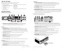
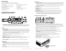
Power Connections
• PAD5000.5FuseSize:2x40AMPATC
• Powerconnectionsacceptupto4AWGwire.
• 4AWGpowerandgroundwirerecommendedforoptimalperformance.
• Connect+12Vtothebatterythroughfuseholder.Thisconnectionprovides
+12Vmainpowertotheamplifier.
• Powerwiremustbefusedwithin12"ofthebattery.
• Groundtheamplifierusingagoodchassisgroundascloseaspossibletotheamplifier.
• ConnectREMterminaltoremoteturn-onleadfromtheheadunit.Thisconnection
provides+12Vpowertoturn-ontheamplifier.
• Addextragroundwirebetweenthenegativeterminalofthebatteryandthechassis.
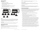
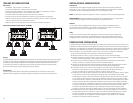
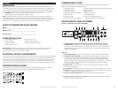
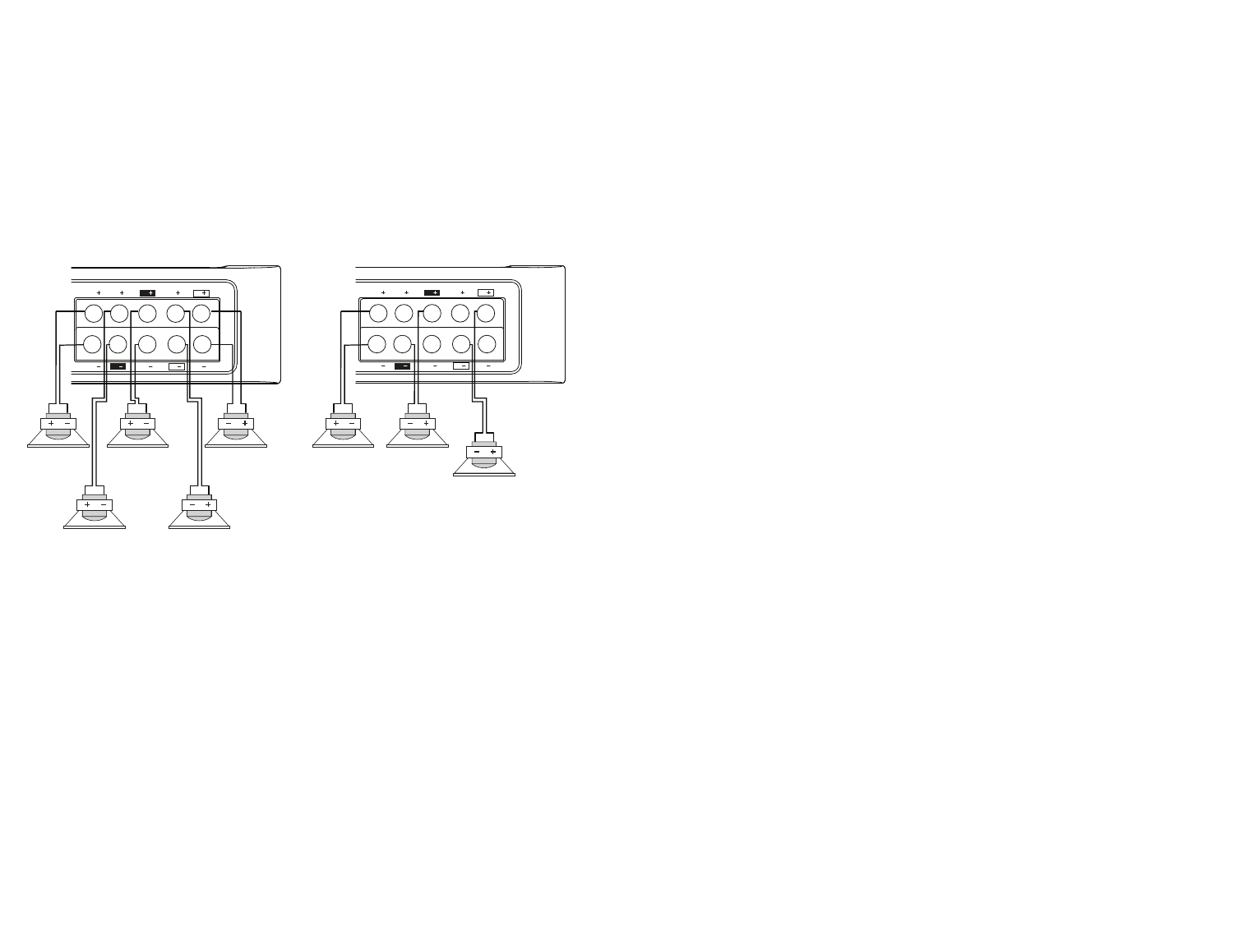
Speaker Wiring Diagram PA D5000.5
Bridging
The amplifier is capable of bridging two full range channels into a single full range channel with higher output power.
For instance, the front channels (FL and FR) when wired as shown will increase the output power from 70W per channel
to 200W per channel (for a 4 Ohm load). The same is true for the rear channels (RL and RR). You can do it with the front
or rear channels, or both. The most common configurations are shown in the figure above: four full range channels
and a subwoofer channel, or two bridged full range channels and a subwoofer channel.
Internal Bridging
Terminals that can be used in bridging mode are identified by the black and outlined boxes next to each terminal.
The two black boxes and the two outlined boxes work together to create an internally bridged hookup.
AMPLIFIER INSTALLATION
Mounting Locations
The location of your amplifier will depend on several important issues. Due to the low profile and compact
size of the Polk Audio PA D Series amplifier, there are many possible installation locations that will yield satisfactory
amplifier performance. Always mount the amplifier in a place that protects the amplifier from the elements.
In addition, mount the amplifier on a stable, flat surface.
NOTE: Mounting amplifiers upside down is not recommended and may cause premature thermal shutdown.
LL RR
BRIDGED
GND
12VREM
25A 25A
LL RR
BRIDGED
RL FL
RR
REAR
FRONT
FR
RR FR
RL FL
GND
12VREM
40A
GND
12VREM
40A
35A
RL FL
RR
REAR
FRONT
FR
RR FR
RL FL
GND
12VREM
40A
GND
12VREM
40A
35A
RL FL
RR
REAR
FRONT
FR
RR FR
RL FL
RL FL
SUB
RR FR
RR FR
SUB
RL FL
GND
12VREM
40A 40A
RL FL
SUB
RR FR
RR FR
SUB
RL FL
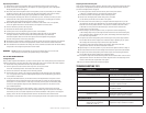
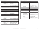
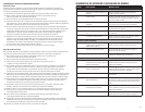
1Ω min 2Ω min
2Ω min
1000.1
4Ω min 2Ω min
2Ω min
2000.2
2Ω min
4000.4
2Ω min
2Ω min
2Ω min
2Ω min
2Ω min4Ω min/bridged
1Ω min 2Ω min
5000.5
1Ω min 4Ω min
2Ω min 2Ω min
2Ω min
4Ω min
4Ω min/bridged
4Ω min/bridged
WARNING! DO NOT mOUNT any amplifier in the engine compartment. Amplifiers are not designed
to endure the harsh environment of an engine compartment.
Passenger Compartment
If you are going to mount the amplifier in the passenger compartment, make sure you have adequate room
forventilation.Whenmountingyouramplifierunderaseatorsimilararea,keepaminimumof1"ofclearance
around the amplifier for adequate cooling.
Trunk Compartment
Mounting your amplifier in the trunk provides excellent performance as long as you do not restrict the airflow
around the heatsink of the amplifier. For optimal results, mount the amplifier with as much clearance as possible.
This type of mounting will yield the best cooling due to the convection effect of the amplifier chassis.
INSTALLATION GUIDELINES
Power for systems with a single amplifier can be supplied by most automotive electrical systems. Systems with multiple
amplifiers may require a higher capacity battery, alternator or the use of a storage capacitor. Polk Audio PA D Series
amplifiers do generate a certain amount of heat as part of normal operation. Be sure the area around the amplifier
is unobstructed to allow adequate air circulation. Remember, beach blankets, last week’s laundry, school books
and homework papers placed on top of the amplifier impede air flow and may cause damage.
1. Please read this owner’s manual carefully before installing your amplifier.
2. Disconnect the battery ground terminal prior to making any electrical connections.
3. Check for any hazards or obstructions such as gas tanks, fuel or brake lines, and wiring harnesses
before mounting the amplifier.
4. Pick a mounting location that will provide adequate access and ventilation and protect the amplifier
from heat, moisture, and dirt.
5. Avoid sharp metal areas when routing cables to the amplifier, and run RCA cables away
from the power cables and other potentially noisy car harnesses.
6. The amplifier should be grounded with a short, heavy gauge wire connected directly to the car
at a bare metal surface, preferably scraped body metal. Do not use factory ground locations,
seat bolts, or brackets that are spot welded.
7. Always fuse your power connection within 12 inches of the battery terminal. Use a fuse or circuit breaker
rated slightly more than the on-board fuse(s) of the amplifier(s). The gauge of power wire used should take
into account the total current draw of the system, and the length of wire used. IASCA and other auto sound
competition organizations have charts available for this; you can also find a chart in the MECP study guide.
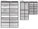
Minimum wire gauge recommendations for the individual amplifiers are listed on the specification page.
Always use the same gauge wire for the amplifier ground that you use for the power wire. Be sure
to examine the battery ground cable of the vehicle, and if necessary, upgrade it by adding an additional
ground wire that is the same gauge as the amplifier’s power wire. Remember, the amplifier can only
deliver its rated output when it is not current limited by the power and ground supply wires.
8. This amplifier is designed to drive a speaker load that measures from 2 to 8 Ohms for full range channels
and 1 Ohm for subwoofer channel. Keep in mind that heat is the long-term enemy of automotive electronics
and the lower your speaker load, the more heat is generated. For low-impedance speaker applications
or restricted ventilation installations, an external cooling fan may be advisable.
9. Battery and ground connections to the vehicle should be made with crimped ring terminals of the appropriate
size (surface area is what counts;) soldering the terminals after crimping is also recommended.
10. Due to the high-frequency MOSFET switching power supply, filtering the power cable is not generally required
(remember that the amp can’t deliver full output if the power supply is restricted.) Proper grounding of the
signal source is mandatory for the amplifier to reach its performance peak. If the RCA inputs are not grounded
adequately via the signal source, electrical noise from the vehicle may be picked up in the system.