41
DSR Series
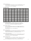
DATA No.2/BIT-4 : JOG
BIT-4 will be set to “1” when the DEVICE receives the “2X.11 : JOG FWD” or “2X.21 :
JOG REV”, command and goes into the JOG mode.
DATA No.2/BIT-3 : VAR
BIT-3 will be set to “1” when the DEVICE is receives “2X.12 : VAR FWD” or “2X.22 :
VAR REV”, command and goes into the VAR mode.
DATA No.2/BIT-2 : TAPE DIRECTION
BIT-2 shows the tape direction defined in the DEVICE.
0 = FWD
1 = REV
DATA No.2/BIT-1 : STILL
BIT-1 will be set to “1” when the DEVICE is STOP mode or STILL mode of SHUTTLE/
JOG/VAR.
DATA No.2/BIT-0 : CUE UP COMPLETE
BIT-0 will be set to “1” when the DEVICE receives “20.30 : PREROLL” and “24.31 : CUE
UP WITH DATA” commands and then cue-up operation is completed successfully.
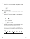
DATA No.3
DATA No.3/BIT-7 : AUTO MODE
BIT-7 will be set to “1” when the DEVICE receives the “40.41 : AUTO MODE ON” com-
mand.
DATA No.3/BIT-3 : AUDIO OUT
DATA No.3/BIT-2 : AUDIO IN
DATA No.3/BIT-1 : OUT
DATA No.3/BIT-0 : IN
When the DEVICE receives ENTRY, PRESET and RECALL commands of each editing point
(IN, OUT, AUDIO IN or AUDIO OUT), the corresponded bit will be set to “1”, and TIMER-1
or TIME CODE data is memorized.
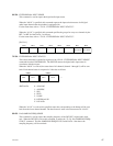
DATA No.4
DATA No.4/BIT-7 : SELECT EE ON
BIT-7 will be set to “1” when the DEVICE receives the “4X.30 : EDIT PRESET” command,
and furthermore, receives the “20.63” : SELECT EE ON” command.
DATA No.4/BIT-6 : FULL EE ON
BIT-6 will be set to “1” when the DEVICE receives the “20.61 : FULL EE ON” command.
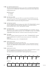
DATA No.4/BIT-4 : EDIT
BIT-4 will be set to “1” when the DEVICE is in the EDIT mode, and at the same time, the
“DATA No.1/BIT-1 : REC” is also set to “1”.


