


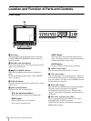
Location and Function of Parts and Controls
10
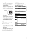
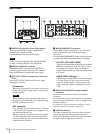
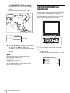
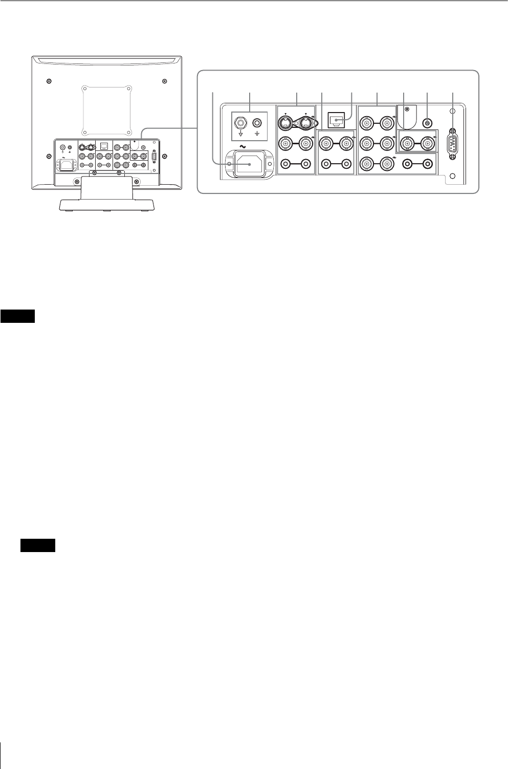
Rear Panel
a OPTION IN connector (D-sub 9-pin, female)
When optional SDI input adaptor BKM-320D is
connected, SDI signals are input.
Press the SDI button to monitor the signal.
Note
Do not install the equipment other than BKM-320D.
It causes to damage the unit or the equipment.
b OPTION AUDIO IN connector
If the BKM-320D is installed in the OPTION IN
connector, input an audio signal into this connector.
Press the SDI button to monitor the audio signal.
c EXT SYNC IN/OUT (external sync) connectors
(BNC)
Press the EXT SYNC button to use the sync signal
through this connector.
IN connector
When this unit operates on an external sync signal,
connect the reference signal from a sync generator
to this connector.
Note
When inputting a video signal with the jitters, etc.
the picture may be disturbed. We recommend using
the TBC (time base corrector).
OUT connector
Loop-through output of the IN connector. Connect
to the external sync input of video equipment to be
synchronized with this unit.
When the cable is connected to this connector, the
75-ohm termination of the input is automatically
released, and the signal input to the IN connector is
output from this connector.
d RGB/COMPONENT connectors
Analog RGB signal or component (Y, P
B, PR) signal
input connectors and their loop-through output
connectors.
Press the RGB/COMPONENT button on the front panel
to monitor the signal input through these connectors.
G/Y, B/P
B, R/PR IN/OUT (BNC)
These are the input/output connectors for an analog
RGB and a component (Y, P
B, PR) signal. Unless
an external sync signal is input, the monitor is
synchronized with the sync signal contained in the
G/Y signal.
AUDIO IN/OUT (RCA pin)
When using an analog RGB or a component signal
as a video signal, use these jacks for the input/
output of an audio signal. Connect them to the
audio input/output jacks on equipment such as a
VCR.
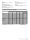
e PARALLEL REMOTE terminal (modular
connector)
Forms a parallel switch and controls the monitor
externally.
For safety, do not connect the connector for peripheral
device wiring that might have excessive voltage to this
modular connector.
For details on the pin assignment and factory setting
function assigned to each pin, see page 21.
f LINE B connectors
Line input connectors for composite video and audio
signals and their loop-through output connectors.
Press the LINE B button on the front panel to monitor
the signal input through these connectors.
LINE A
LINE B
PARALLEL REMOTE RGB/COMPONENT
VIDEO
IN OUT
IN
OUT
VIDEO
IN OUT
G/Y
IN OUT
B/P
B
IN OUT
EXT
SYNC
IN OUT
R/P
R
IN OUT
AUDIO
IN OUT
AUDIO
IN OUT
AUDIO
IN OUT
AC IN
OPTION
AUDIO IN
OPTION IN
LINE A
LINE B
PARALLEL REMOTE RGB/COMPONENT
VIDEO
IN OUT
VIDEO
IN OUT
G/Y
IN OUT
B/P
B
IN OUT
EXT
SYNC
IN OUT
R/P
R
IN OUT
AUDIO
IN OUT
AUDIO
IN OUT
AUDIO
IN OUT
AC IN
OPTION
AUDIO IN
OPTION IN
IN
OUT
21345678
9