


38
XR-M510
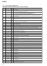
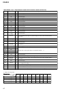
7-16. IC PIN FUNCTION DESCRIPTION
• MAIN BOARD IC601 MB90574BPMT-G-257-BND (SYSTEM CONTROLLER)
Pin No. Pin Name I/O Description
1NCO
Not used (open)
2 AMSIN I
Whether a music is present or not from CXA2510AQ (IC401) is detected at auto music sensor
“L”: music is present, “H”: music is not present
3 AMSON O
Tape auto music sensor control signal output to the CXA2510AQ (IC401)
“L” is output to lower the gain for audio level at FF/REW mode
4 SP LATCH O
Serial data latch pulse output for spectrum analyzer section to the liquid crystal display drive
controller (IC607)
5 ATT
O Audio line muting on/off control signal output terminal “H”: muting on
6 SYSRST O
System reset signal output to the liquid crystal display drive controller (IC607) and SONY bus
interface (IC501) “L”: reset
7 N/R O
Forward/reverse direction control signal output to the CXA2510AQ (IC401)
“L”: forward direction, “H”: reverse direction
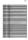
8 VCC —
Power supply terminal (+5V)
9 NIL I
Not used (fixed at “L”)
10 E2PSIO I/O Two-way data bus for tuner EEPROM with the FM/AM tuner unit (TUX100)
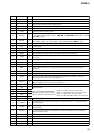
11
E2PCKO I/O
Two-way bus clock signal for tuner EEPROM with the FM/AM tuner unit (TUX100)
12 FLS SI I
Flash memory write data input from the liquid crystal display drive controller (IC607)
13 FLS SO O
Flash memory write data output to the liquid crystal display drive controller (IC607)
14 BUS-ON
O
Bus on/off control signal output to the liquid crystal display drive controller (IC607) and SONY
bus interface (IC501) “L”: bus on
15
BEEP O Beep sound drive signal output terminal
16
TELATT I Telephone detection signal input terminal At input of “H”, the signal is attenuated by –20 dB
17 UNISI
I Serial data input from the SONY bus interface (IC501)
18 UNISO
O Serial data output to the SONY bus interface (IC501)
19 UNICKO
O
Serial clock signal output to the liquid crystal display drive controller (IC607) and SONY bus
interface (IC501)
20 IFWIDTH O
Not used (open)
21, 22 NC O Not used (open)
23 MTLOUT O METAL on/off control signal output to the CXA2510AQ (IC401) “H”: METAL on
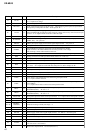
24
SIRCS
I
Sircs remote control signal input from the remote control receiver (IC900, 903)
25 DSPSI I
Not used (open)
26 DSPSO
O Not used (open)
27 DSPCKO
O Not used (open)
28 DSPPLL
O Not used (open)
29 DSPMST
O Not used (open)
30 SHIFT
O Not used (open)
31 VOLATT
O
Pre amplifier muting on/off control signal output to the electrical volume (IC100)
“L”: muting on
32 TUATT O
Muting on/off control signal output of the FM/AM tuner signal “L”: muting on
33
VSS
—
Ground terminal
34 C —
Connected to coupling capacitor for the power supply
35 DSPLAT O
Not used (open)
36 DSPRST O
Not used (open)
37 ANT CUT
O
Tuner system power supply on/off control signal output terminal “H”: tuner power on
Not used (open)
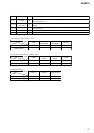
38 DVCC —
Power supply terminal (+5V) (for D/A converter)
39 DVSS —
Ground terminal (for D/A converter)