


45
XR-M510
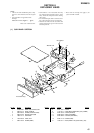
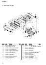
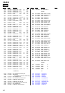
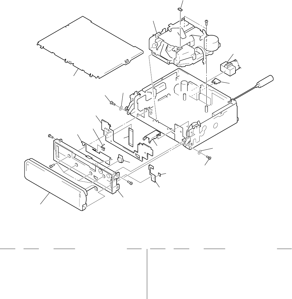
(1) SUB PANEL SECTION
SECTION 8
EXPLODED VIEWS
• Items marked “*” are not stocked since they
are seldom required for routine service. Some
delay should be anticipated when ordering
these items.
• The mechanical parts with no reference num-
ber in the exploded views are not supplied.
• Hardware (# mark) list and accessories and
packing materials are given in the last of the
electrical parts list.
NOTE:
• -XX and -X mean standardized parts, so they
may have some difference from the original
one.
• Color Indication of Appearance Parts
Example:
KNOB, BALANCE (WHITE) . . . (RED)
↑↑
Parts Color Cabinet's Color
• Please refer to servicing notes (page 3) for
system of TYPE A and B.
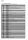
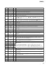
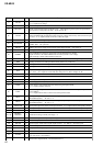
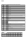
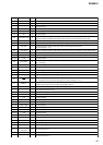
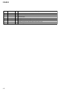
Ref. No. Part No. Description Remark
Ref. No. Part No. Description Remark
1 X-3380-205-1 PANEL (XR) SUB ASSY, SUB
2 3-044-475-11 DOOR, CASSETTE
3 3-044-482-01 SPRING (CASSETTE DOOR)
4 3-044-478-01 BUTTON (EJECT) (Z)
* 5 1-680-701-11 SUB BOARD
6 1-783-268-31 CABLE, FLAT
7 3-045-756-01 SCREW (PANEL)
* 8 3-041-156-11 COVER
9 1-776-527-71 CORD (WITH CONNECTOR) (ISO) (POWER)
* 10 3-045-762-01 COVER (FLEXIBLE)
* 11 3-048-640-01 SHEET (SUB PANEL)
* 12 3-049-388-01 CUSHION (SUB PANEL)
13 3-049-771-01 SPACER (ARM)
F1 1-532-877-11 FUSE (BLADE TYPE) (AUTO FUSE) (10A)
2
Front Panel assy
F1
#1
#1
#1
not supplied
#1
3
5
7
13
9
8
7
10
11
12
6
4
1
MG-25E-136
13