


39
XR-M510
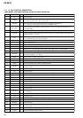
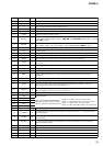
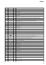
Pin No. Pin Name I/O Description
40 MREF O
Front panel open/close motor (M601) speed control signal output to the BA6288FS (IC502)
41 NC O
Not used (open)
42 AVCC
— Power supply terminal (+5V) (for analog system)
43 AVRH
I Reference voltage (+5V) input terminal (for A/D converter)
44 AVRL
I Reference voltage (0V) input terminal (for A/D converter) Not used (fixed at “L”)
45 AVSS
— Ground terminal (for analog system)
46 KEYIN0
I
Key input terminal (A/D input) (LSW901 to LSW912, S900)
TA, SOUND, D-BASS, MENU, DISC +, . m, LIST, > M, ENTER, DISC –, CLOSE,
OPEN, Z keys input
47 KEYIN1
I
Key input terminal (A/D input) (LSW913 to LSW919, LSW921 to LSW925, S902)
6 to 3, SHUF 2, REP 1, AF, +, PTY DSPL, –, OFF, SOURCE, MODE o keys input
48 RCIN0
I Rotary remote commander key input terminal (A/D input)
49 NC O
Not used (open)
50 QUALITY
I Noise level detection signal input at SEEK mode (A/D input)
51
FMAGC I
FM AGC detection signal input from the FM/AM tuner unit (TUX100) (A/D input)
52 MPTH
I Multi-path detection signal input from the RDS decoder (IC700) (A/D input)
53
VSM I
FM and AM signal meter voltage detection input from the FM/AM tuner unit (TUX100)
(A/D input)
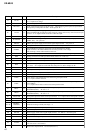
54 VCC —
Power supply terminal (+5V)
55 ST-BY
O Standby on/off control signal output terminal “L”: standby mode, “H”: amplifier on
56 NS-MASK O
Discharge control signal output for the noise detection circuit “H”: discharge
57 REEL I
Rotation detect signal input from supply reel sensor and take-up reel sensor on the deck
mechanism
58 OPEN I
Not used (open)
59 TAPE ON O
Tape system power supply on/off control signal output terminal “H”: tape on
60 LMEJ O
Motor drive signal output to the loading/tape operation motor drive (IC400) “H” active
(For the eject direction and reverse side operation) *1
61 LMLOD O
Motor drive signal output to the loading/tape operation motor drive (IC400) “H” active
(For the loading direction and forward side operation) *1
62 CM ON O
Capstan/reel motor (M901) drive signal output terminal “H”: motor on
63 VSS —
Ground terminal
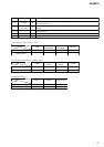
64 POS0 I
65 POS1 I
66 POS2 I
67 POS3 I
68 NC O
Not used (open)
69
FLASH-W
I
Internal flash memory data write mode detection signal input terminal “L”: data write mode
Not used (pull up)
70 I2CSIO I/O
Two-way data I
2
C bus with the FM/AM tuner unit (TUX100), RDS decoder (IC700) and electrical
volume (IC100)
71 I2CCKO O
I
2
C bus clock signal output to the FM/AM tuner unit (TUX100), RDS decoder (IC700) and
electrical volume (IC100)
72 RCIN1
I Rotary remote commander shift key input terminal
73 X1A O
Sub system clock output terminal (32.768 kHz)
74 X0A I
Sub system clock input terminal (32.768 kHz)
75 DAVN I
Data transmit completed detection signal input from the RDS decoder (IC700) “H” active
76 CDON-IN I
CD/MD on/off control signal input terminal (fixed at “L” in this set)
Tape position (EJECT/FF/REW/REV/
FWD mode) detect input from the tape
operation switch on the deck mechanism
POS0: “L”: EJECT mode, “H”: others mode
POS1: “L”: FF and FWD mode, “H”: others mode
POS2: “L”: REW mode, “H”: others mode
POS3: “L”: REV and EJECT mode, “H”: others mode