


Reference Guide: TT128x High Definition Professional Receiver/Decoder Page 2-1
ST.RE.E10141.5
Chapter 2
2. Installing the Equipment
Contents
2.1 Read This First!......................................................... 2-3
2.1.1 Handling .......................................................2-3
2.1.2 Installing the Equipment ............................... 2-3
2.1.3 Lifting............................................................2-3
2.1.4 Site Requirements........................................2-3
Power Supplies............................................. 2-3
Environment .................................................2-3
Lightning Protection...................................... 2-3
2.2 Preliminary Checks................................................... 2-4
2.2.1 Mechanical Inspection..................................2-4
2.2.2 Moving the Equipment Safely....................... 2-4
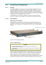
2.3 Installing the Equipment............................................ 2-5
2.3.1 Fixing............................................................2-5
2.3.2 Ventilation..................................................... 2-5
Openings in the Covers................................2-5
Care in Positioning .......................................2-5
Protection from Moisture ..............................2-6
2.3.3 Installing Cables - Safety.............................. 2-6
2.4 EMC Compliance Statements................................... 2-6
2.4.1 EN 55022/AS/NZS 3548............................... 2-6
2.4.2 FCC .............................................................. 2-6
2.5 AC Supply Operating Voltage and Fusing - Safety
Information................................................................2-6
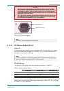
2.5.1 AC Power Supply .........................................2-6
2.5.2 AC Power Supply Cord................................. 2-7
General......................................................... 2-7
Wire Colours................................................. 2-7
2.5.3 Connecting the Equipment to the AC
Power Supply ...............................................2-8
2.6 -48 Vdc Power Supply...............................................2-8
2.6.1 DC Power Supply ......................................... 2-8
2.6.2 Location of the DC Input Connector..............2-8
2.6.3 Connecting the Equipment to the DC
Power Supply................................................2-9
2.7 Protective Earth/Technical Earth...............................2-9
2.8 Signal Connections..................................................2-10
2.8.1 General .......................................................2-10
2.8.2 ASI Out .......................................................2-12
2.8.3 Audio Outputs .............................................2-12
2.8.4 SVGA Output (RGB HV).............................2-13
2.8.5 Digital Video Output....................................2-13
2.8.6 Frame Synchronisation...............................2-14
2.8.7 Ethernet ......................................................2-14
2.8.8 Alarm Connector and Relay........................2-15
2.8.9 RS-232 Low-speed Asynchronous and
RS-422 High-speed Synchronous Data
Outputs .......................................................2-15
2.9 Option Card Connectors..........................................2-16
List of Figures
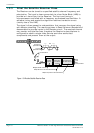
Figure 2.1: Air Flow Through the Equipment................................. 2-5
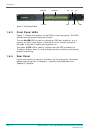
Figure 2.2: AC Power Inlet Assembly............................................ 2-7
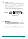
Figure 2.3: Location of the Technical Earth................................... 2-9
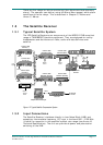
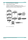
Figure 2.4: Typical Decoder Rear Panel ..................................... 2-10
Figure 2.5: Signal Connections.................................................... 2-11
List of Tables
Table 2.1: Supply Cord Wiring Colours ......................................... 2-7
Table 2.2: Non Standard Supply Cord Wire Colours..................... 2-8
Table 2.3: ASI Out Connector...................................................... 2-12
Table 2.4: Analogue Audio Connectors....................................... 2-12
Table 2.5: SVGA Connector........................................................2-13
Table 2.6: Digital Output Connector ............................................ 2-13
Table 2.7: Frame Sync Hi-Z Connector....................................... 2-14
Table 2.8: Ethernet Pin-outs........................................................ 2-14