


E6580772
10
3. Functional description
In this section, functions added by the installation of this F10M option unit, on top of the standard inverter
functions, are described.
3.1 F10M communication function
Through the communication network, drive and stop control and concentrated monitoring control of operation
status can be carried out by the programmable controller and industrial computer.
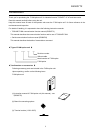
3.1.1 Connection of transmission cable
z SL1, SL2, SG
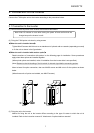
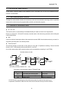
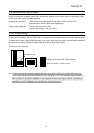
Transmission path is constructed by the shielded twisted pair cables as shown in the figure below.
Be sure to connect SL1, SL2 and SG mutually to another station. Note that wrong connection will not bring the
correct transmission.
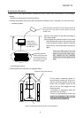
z SHD
Connect a shield of twisted pair cable to the transmission terminal SHD of each station and set up a class 3 or
equivalent grounding work in an arbitrary station.
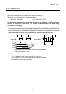
z Terminal resistor
Set terminal resistors at both sides of the system for the sake of impedance matching. Connect terminal
resistor (120Ω-1/2W) between the terminal block SL1 and SL2.
(As for the master station (MS), terminal resistor can be combined by connecting L1 and TERM.)
Grounding / Earthing
(Grounding / earthing resistance 100 max.)
Terminal resistor
120 -1/2W
Shielded twisted pair cable
Connection of communication cable of TOSLINE F10M
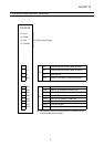
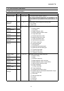
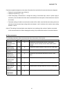
Signal name Name Detail
SL1 Transmitting and receiving data Positive line
SL2 Transmitting and receiving data Negative line
SG Signal ground Ground of signal line
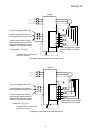
•
Do not connect a grounding line of the shield and a power line earth of the inverter or so.
•
Separate a transmission cable from the main circuit connection wire by more than 200mm.