


E6580772
16
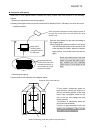
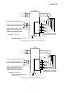
3.2.2 Connection of PG
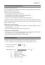
As for the pulse input signals, PGA1 and PGA2 are connected for Phase A, PGB1 and PGB2 are
connected for Phase B, and PGZ1 and PGZ2 are connected for Phase Z.
(The wiring for Phase Z is done only when using Z-marker is necessary.)
The polarity of the pulse input signals should be as follows:
+ side: PGA1, PGB1, PGZ1 - side: PGA2, PGB2, PGZ2
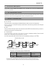
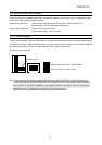
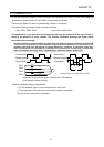
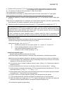
The signal which is fed back from the encoder should have the waveform of the figure below in
terms of the direction of motor rotation. The encoder installation direction and signal wiring
should be done accordingly.
Forward rotation or reverse rotation is judged from the feedback pulses of Phase A and Phase B
(2-phase pulse that have 90 degrees of phase difference). Therefore, it should be noted that,
when connections are wrong, there is possibility for abnormal rotation of the motor.
A
A
B
B
PGA1
PGA2
PGB1
PGB2
↑V
A
↑V
B
X
2
X
1
X
3
X
4
T
Phase difference:Xn≧0.15T(n=1,2,3,4)
Phase A(VA)
Forward rotation
Phase B(VB)
Phase A(VA)
Reverse rotation
Phase B(VB)
Judgement on normal and reverse rotations by the PG feedback
of two phases (Phases A and B)
<When PG feedback signal is single phase>
1. For PG feedback signal, connect terminals PGA1 and PGA2.
2. The judgement on forward rotation and reverse rotation is impossible.
Only the speed control mode is applicable.