


E6580772
6
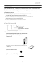
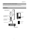
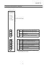
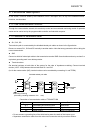
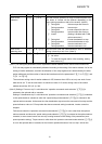
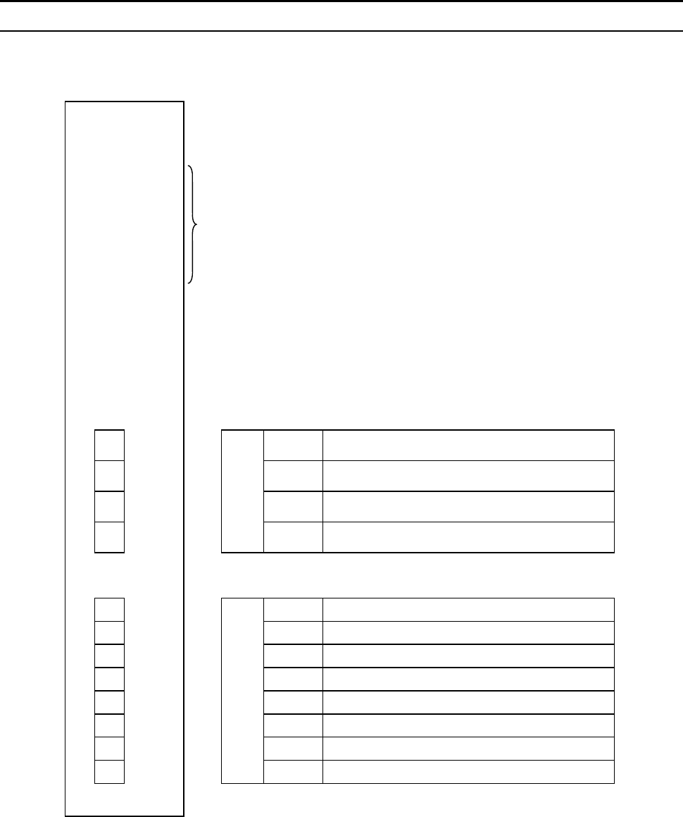
1.2 Name of each section (terminal)
1 SL1 SL1 Transmitting and receiving data (positive)
2 SL2 SL2 Transmitting and receiving data (negative)
3 SG SG Signal ground
4SHD
TB1
SHD Terminal for shield (no connection inside)
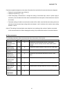
1 PGA1 PGA1 Phase A, PG feedback anode side
2 PGA2 PGA2 Phase A, PG feedback cathode side
3 PGB1 PGB1 Phase B, PG feedback anode side
4 PGB2 PGB2 Phase B, PG feedback cathode side
5 PGZ1 PGZ1 Phase Z, PG feedback anode side
6 PGZ2 PGZ2 Phase Z, PG feedback cathode side
7 PGVC PGVC 12V power supply
8PGCC
TB2
PGCC Common terminal for control signal *1
*
1: Connect this PGCC terminal to the CC terminal on the
control board of the inverter.
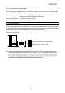
TLF001Z
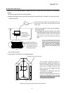
RUN
SCAN
AUX
POWER
○
○
○
○
LED for status display