63230-300-212 List of Tables
April 2001
ix
© 2001 Schneider Electric All Rights Reserved
Table 1–1: SummaryofCircuitMonitorInstrumentation............ 2
Table 1–2: Circuit Monitor Parts, Accessories, and Custom Cables . . . 3
Table 3–1: FactoryDefaultsfortheDisplaySettings.............. 14
Table 3–2: OptionsforCommunicationsSetup.................. 15
Table 3–3: OptionsforMeterSetup........................... 17
Table 3–4: OptionsforCreatinganAlarm...................... 20
Table 3–5: OptionsforEditinganAlarm ....................... 22
Table 3–6: I/ODescriptions................................. 24
Table 3–7: OptionsforPasswordSetup........................ 27
Table 3–8: OptionsforCustomQuantities...................... 30
Table 3–9: Available Default Quantities ........................ 33
Table 3–10: OptionsforAdvancedMeterSetup .................. 36
Table 3–11: Read/WriteRegisterOptions....................... 44
Table 3–12: Wiring Error Messages............................ 48
Table 4–1: One-Second, Real-Time Readings Samples ........... 52
Table 4–2: 100msReal-TimeReadings....................... 53
Table 4–3: DemandReadings............................... 56
Table 4–4: EnergyReadings ................................ 64
Table 4–5: PowerAnalysisValues............................ 68
Table 5–1: I/O Extender Options ............................. 70
Table 5–2: Sample register readings for analog inputs ............ 74
Table 5–3: Sample register readings for analog output ............ 82
Table 6–1: Scale Groups ................................... 91
Table 6–2: ScaleGroupRegisterNumbers..................... 92
Table 6–3: ListofDefaultAlarmsbyAlarmNumber .............. 94
Table 6–4: AlarmTypes.................................... 96
Table 7–1: Values Stored in Maintenance Log ................. 103
Table 8–1: Available Resolutions for Disturbance Waveform
Captures...................................... 108
Table 8–2: Available Resolutions for Adaptive Waveform
Captures...................................... 109
Table 8–3: 100ms rms Quantities ........................... 110
Table 9–1: Capability of the circuit monitor to measure electromagnetic
phenomena . .................................. 117
Table 10–1: Troubleshooting . . . ............................. 125
Table A–1: DateandTimeFormat........................... 129
Table A–2: DateandTimeByteExample...................... 129
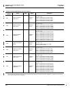
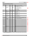
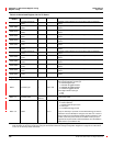
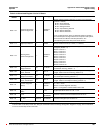
Table A–3: AbbreviatedRegisterList......................... 130
Table A–4: AbbreviatedRegisterListforI/OStatus.............. 166
Table A–5: Registers for Alarm Position Counters . . . ............ 173
Table A–6: Spectral Components............................ 178
Table B– 1: Locationofthecommandinterface ................. 182
Table B– 2: CommandCodes............................... 183
Table B– 3: RegistersforHarmonicCalculations................ 190
LIST OF TABLES