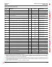
63230-300-212 Appendix A—Abbreviated Register Listing
April 2001 Register Listing
145
© 2001 Schneider Electric All Rights Reserved
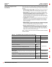
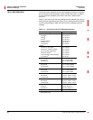
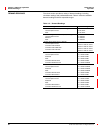
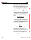
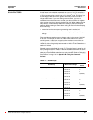
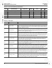
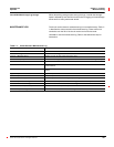
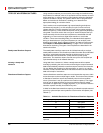
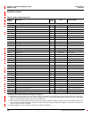
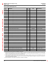
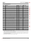
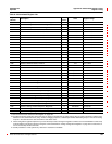
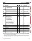
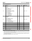
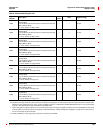
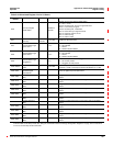
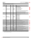
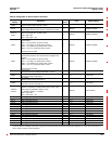
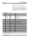
Demand
1800
Demand Calculation Mode, Current
0 = Thermal Demand (default)
——0
1801
Demand Interval, Current — Minutes 1 to 60, Default = 15
1802
Demand Subinterval, Current — Minutes 1 to 60, Default = 1
1803
Demand Sensitivity, Current
Adjusts the sensitivity of the thermal demand calculation.
— 1% 1to99,Default=90
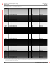
1805
Short Demand Interval, Current
Sets the interval for a running average demand calculation of
short duration.
— Seconds 0 to 60, Default = 15
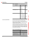
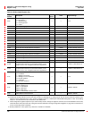
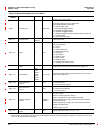
1806 Time Elapsed in Present Demand Interval, Current — Seconds 0 to 3,600
1807 Time Elapsed in Present Demand Subinterval, Current — Seconds 0 to 3,600
1808 Interval Count, Current — 1.0 0 to 32,767
1809 Subinterval Count, Current — 1.0 0 to 60
1810 to 1813 Min/Max Reset Date/Time, Current — See Template See Template
1814 Min/Max Reset Count, Current — 1.0 0 to 32,767
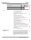
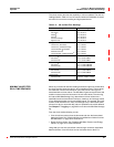
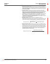
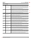
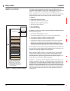
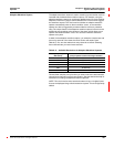
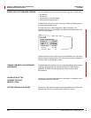
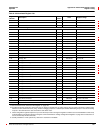
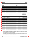
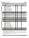
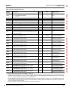
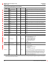
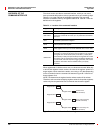
1820
Demand Calculation Mode, Voltage
0 = Thermal Demand (default)
1 = Timed Interval Sliding Block
2 = Timed Interval Block
4 = Timed Interval Rolling Block
8 = Input Synchronized Block
16 = Input Synchronized Rolling Block
32 = Command Synchronized Block
64 = Command Synchronized Rolling Block
128 = Clock Synchronized Block
256 = Clock Synchronized Rolling Block
512 = Slave to Power Demand Interval
1024 = Slave to Incremental Energy Interval
——0to1024
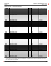
1821
Demand Interval, Voltage — Minutes 1 to 60, Default = 15
1822
Demand Subinterval, Voltage — Minutes 1 to 60, Default = 1
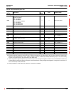
1823
Demand Sensitivity, Voltage
Adjusts the sensitivity of the thermal demand calculation.
— 1% 1to99,Default=90
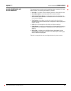
1825
Short Demand Interval, Voltage
Sets the interval for a running average demand calculation of
short duration.
— Seconds 0 to 60, Default = 15
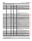
1826 Time Elapsed in Interval, Voltage — Seconds 0 to 3,600
1827 Time Elapsed in Subinterval, Voltage — Seconds 0 to 3,600
1828 Interval Count, Voltage — 1.0 0 to 32,767
1829 Subinterval Count, Voltage — 1.0 0 to 60
1830 to 1833 Min/Max Reset Date/Time, Voltage — See Template See Template
1834 Min/Max Reset Count, Voltage — 1.0 0 to 32,767
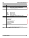
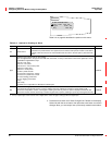
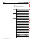
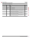
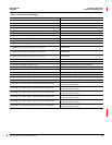
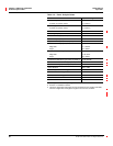
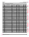
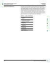
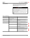
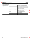
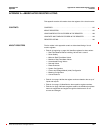
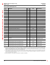
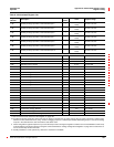
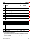
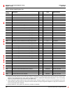
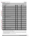
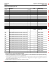
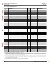
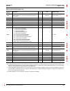
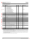
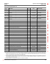
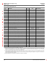
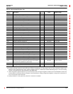
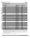
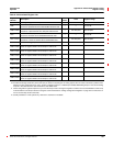
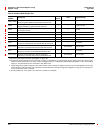
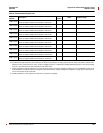
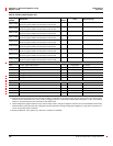
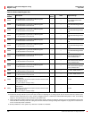
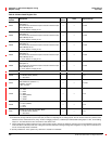
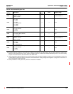
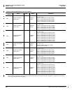
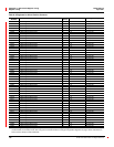
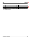
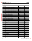
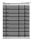
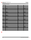
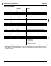
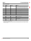
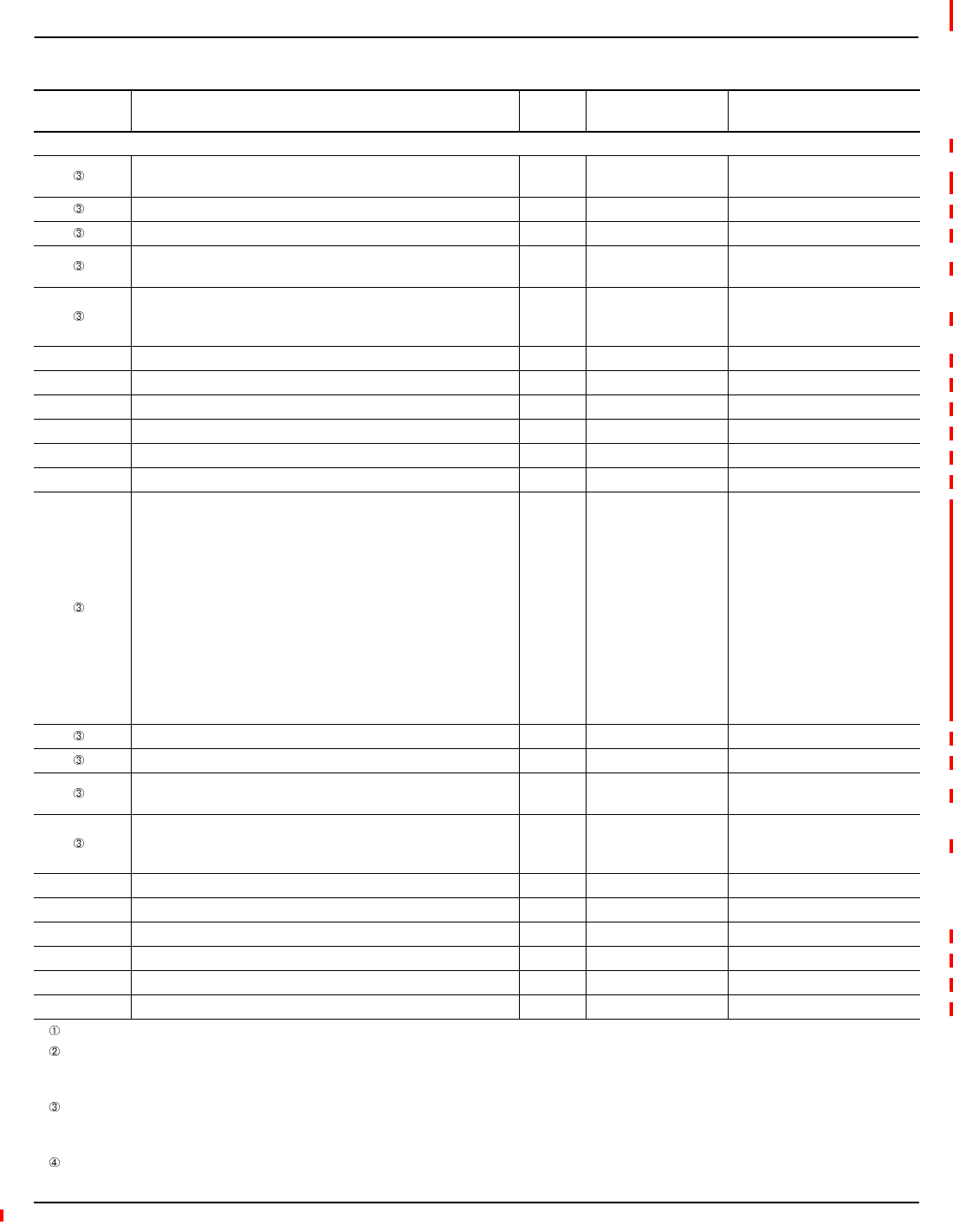
Table A–3:Abbreviated Register List
Register
Number
Description
Scale
Factor
Units Register Range
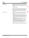
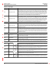
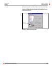
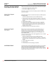
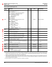
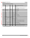
See “How Power Factor is Stored in the Register” on page 128.
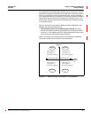
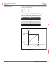
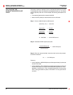
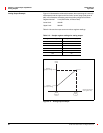
The alternate storage method for power factor (PF) is useful for outputting PF on analog outputs. The PF value is stored as a positive value
between 0 and 2, centered around 1 (unity). A value of 0 lagging maps to 0; -0.999 maps to 0.999;0.999 leading maps to 1.001; and 0 leading
maps to 2. The alternate PF is also stored with a scale factor 0.001.
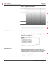
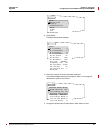
These configuration registers require that you enter the setup mode to change the register’s contents. Issue command 9020 to enter setup
mode and 9021 to exit setup mode. See “Using the Command Interface to Change Configuration Registers” on page 187 for instructions on
how to use the setup-mode commands.
Quantity available for 4-wire system only. Value set to -32,768 if not available.