


49-EN
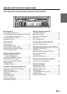
Installation and Connections
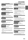
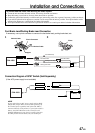
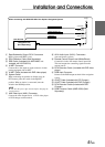
1 Antenna Receptacle
2 Remote Control Interface Connector
Connect to the remote control interface box.
3 Remote Control Output Lead (White/Brown)
Connect this lead to the remote control input lead.
This lead outputs the controlling signals from the
remote control.
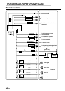
4 Foot Brake Lead
Connect to the vehicle’s foot brake lead or brake lamp
lead.
5 Power Supply Connector
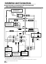
6 System Switch
When connecting an equalizer or divider using Ai-
NET feature, place this switch in the EQ/DIV
position. When no device is connected, leave the
switch in the NORM position.
NOTE
Be sure turn the power off to the unit before changing the
switch position.
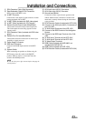
7 Illumination Lead (Orange)
This lead may be connected to the vehicle’s
instrument cluster illumination lead. This will allow
the backlighting of the CVA-1003 to dim whenever
the vehicle‘s lights are turned on.
8 Remote Turn-On Lead (Blue/White)
Connect this lead to the remote turn-on lead of your
amplifier or signal processor.
9 Power Antenna Lead (Blue)
Connect this lead to the +B terminal of your power
antenna, if applicable.
! Audio Interrupt In Lead (Pink/Black)
" Parking Brake Lead (Yellow/Blue)
Connect this lead to the power supply side of the
parking brake switch to transmit the parking brake
status signals to the CVA-1003.
# Switched Power Lead (Ignition) (Red)
Connect this lead to an open terminal on the vehicle’s
fuse box or another unused power source which
provides (+) 12V only when the ignition is turned on
or in the accessory position.
$ Battery Lead (Yellow)
Connect this lead to the positive (+) post of the
vehicle’s battery.
% Fuse Holder (15A)
& Ground Lead (Black)
Connect this lead to a good chassis ground on the
vehicle. Make sure the connection is made to bare
metal and is securely fastened using the sheet metal
screw provided.
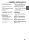
( Right Front (+) Speaker Output Lead (Gray)
) Right Front (–) Speaker Output Lead (Gray/
Black)
~ Right Rear (–) Speaker Output Lead (Violet/
Black)
+ Right Rear (+) Speaker Output Lead (Violet)
, Left Rear (+) Speaker Output Lead (Green)
- Left Rear (–) Speaker Output Lead (Green/
Black)
. Left Front (–) Speaker Output Lead (White/Black)
/ Left Front (+) Speaker Output Lead (White)
: RGB input Connector