


(No.MA165)1-11
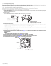
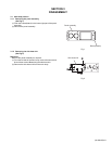
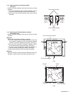
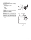
3.1.4 Removing the front chassis assembly
(See Fig.7)
• Remove the panel assembly, side heat sink and top chassis
assembly.
(1) From the both sides of the top chassis assembly, remove
the two screws E attaching the front chassis assembly.
(2) Remove the front chassis assembly from the top chassis
assembly.
Fig.7
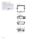
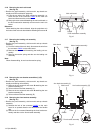
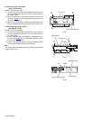
3.1.5 Removing the DVD mechanism assembly
(See Figs.8 and 9)
• Remove the panel assembly, side heat sink and top chassis
assembly.
Reference:
Remove the front chassis assembly as required.
(1) From the inside of the top chassis assembly, remove the
three screws F attaching the DVD mechanism assembly
and take out the DVD mechanism assembly. (See Fig.8.)
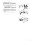
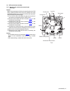
(2) From the side of the DVD mechanism assembly, remove
the double-stick tape fixing the insulator. (See Fig.9.)
(3) From the top side of the DVD mechanism assembly, re-
move the spacer attaching the insulator. (See Fig.9.)
(4) Remove the insulator from the top chassis assembly.
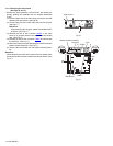
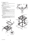
Reference:
When the resolution of DVD mechanism assembly is done se-
quentially, remove the main sub board. (See next Fig.10.)
Fig.8
Fig.9
Front chassis assembly
E E
Top chassis assembly
F
F
DVD mechanism assembly
F
Top chassis assembly
Insulator
Spacer
Double-stick tape
Double-stick tape