


1-14 (No.MA165)
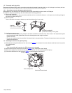
3.1.11 Removing the main board
(See Figs.16 and 17)
• Remove the panel assembly, side heat sink, top chassis as-
sembly, loading unit assembly and arm bracket assemblies
(L)/(R).
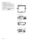
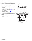
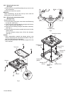
(1) From the back side of the main body, remove the screw P
attaching the rear bracket. (See Fig.16.)
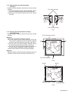
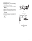
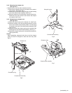
(2) From the top side of the main body, take out the rod gear.
(See Fig.17.)
Reference:
When attaching the rod gear, attach the washers with it
as before. (See Fig.17.)
(3) Release the lock of the connector CN962
on the main
board in an upward direction and disconnect the flexible
wire. (See Fig.17.)
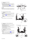
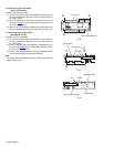
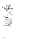
(4) Release the lock of the connector CN891
and disconnect
the card wire. (See Fig.17.)
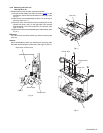
(5) Remove the three screws P attaching the main board to the
bottom chassis assembly. (See Fig.17.)
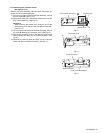
(6) Take out the main board from the bottom chassis assem-
bly.
Reference:
When attaching the main board, attach the main board under
the sections e of the bottom chassis assembly as before. (See
Fig.17.)
Fig.16
Fig.17
Rear bracket
P
Bottom chassis assembly
Main board
e
P
P
e
CN891
Lock
Rod gear
CN962
Lock
Washer
Washer