


(No.MA165)1-13
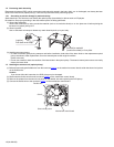
3.1.10 Removing the connector board
(See Figs.13 to 15)
• Remove the panel assembly, side heat sink, top chassis as-
sembly and front bracket assembly.
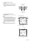
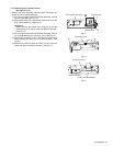
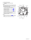
(1) From the front side of the front bracket assembly, remove
the two screws M. (See Fig.13.)
(2) Remove the joints b and remove the detach lever from the
front bracket assembly. (See Fig.13.)
Reference:
When attaching the detach lever, insert the end of the
torsion spring in the hole c of the front bracket assembly.
(See Fig.13.)
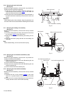
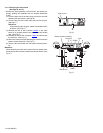
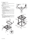
(3) From the back side of the front bracket assembly, remove
the screw N attaching the connector cover. (See Fig.14.)
(4) Remove the connector cover in the direction of the arrow
while releasing the tabs d in an upward direction. (See
Fig.14.)
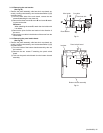
(5) Remove the reinforce plate and take out the connector
board from the front bracket assembly. (See Fig.15.)
Fig.13
Fig.14
Fig.15
M
b
b
c
Detach lever
Front bracket assembly
Torsion spring
N
Connector cover
d
d
Connector board
Reinforce plate
Front bracket assembly