


(No.MA165)1-37
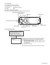
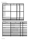
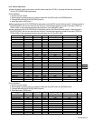
4.6.9 Monitor adjustment
Indication
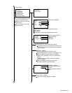
COM AMPLITUDE
BRIGHT GAIN
COLOR GAIN N
COLOR GAIN P
TINT N
TINT P
BLACK LIMITER
BRIGHT
APERTURE
R SUB BRIGHT
B SUB BRIGHT
W PEAK LIMITER
GAMMA1
GAMMA2
CONTRAST
R SUB CONTRAST
B SUB CONTRAST
VCO FREE RUN N
VCO FREE RUN P
PLL STOP POS
V POSITION
H POSITION
PWM FREQUENCY
BRST CLN PLS POS
PWM DUTY
COM DC
DC OUTPUT
Minimum value
0x00
0x00
0x00
0x00
0x00
0x00
0x00
0x00
0x00
0x00
0x00
0x00
0x00
0x00
0x00
0x00
0x00
0x00
0x00
0x00
0x00
0x00
0x00
0x00
0x00
0x00
0x00
Maximum value
0xFF
0xFF
0xFF
0xFF
0xFF
0xFF
0x7F
0xFF
0x7F
0xFF
0xFF
0x7F
0xFF
0xFF
0xFF
0xFF
0xFF
0xFF
0xFF
0x0F
0x07
0x1F
0x0F
0x07
0xFF
0xFF
0xFF
Production jig initial value Reference register value
R/W CHROMA 1
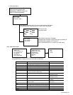
When adjusting, switch on the main unit and insert a test disc (VT-501). And play the test disc and pause it.
(Exit for VCO FREE-RUN adjustment)
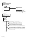
1. Set the service mode 4.
2. Exchanging it operate a menu of a service mode with the [UP] button and [DOWN] button.
3. Change data with the [B.SKIP]/[F.SKIP] buttons.
4. Write data with a [OK] button.
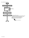
When performing the VCO FREE-RUN N adjustment, set the NTSC mode (Service mode 3 Service mode
DVD NTSC/PAL) and turn the input into the no input. Connect the frequency counter to the point (TP661 or
TP681-GND) on the panel board and set the frequency into 15.62 0.01 (kHz).
When performing the VCO FREE-RUN P adjustment, set the PAL mode (Service mode 3 Service mode
DVD NTSC/PAL) and turn the input into the no input. Connect the frequency counter to the point (TP661 or
TP681-GND) on the panel board and set the frequency into 15.73 0.01 (kHz).
Initial value
0x80
0x80
0x80
0x80
0x80
0x80
0x40
0x80
0x40
0x80
0x80
0x40
0x80
0x80
0x80
0x80
0x80
0x80
0x80
0x00
0x00
0x00
0x08
0x00
0x80
0x80
0x80
0x80
0x80
0x5F
0x62
0x82
0x80
0x5E
0xA3
0x40
0x88
0x88
0x7F
0x80
0xFF
0x64
0x74
0x78
0x8C
0x89
0x08
0x02
0x1F
0x08
0x03
0xFF
0x80
0x65
0x80
0x80
0x60
0x62
0x6D
0x80
0x5E
0xA3
0x40
0x88
0x89
0x7F
0x80
0xFF
0x65
0x71
0x74
0x8F
0x8B
0x08
0x02
0x1F
0x08
0x03
0xFF
0x80
0x43
Fix
Fix
Adjust
Adjust
Adjust
Adjust
Fix
Adjust
Fix
Adjust
Adjust
Fix
Fix
Fix
Adjust
Adjust
Adjust
Adjust
Adjust
Fix
Fix
Fix
Fix
Fix
Fix
Fix
Adjust
15.62 kHz
15.73 kHz
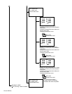
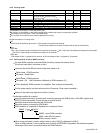
R/W CHROMA 2
1. Set the service mode 4.
2. Exchanging it operate a menu of a service mode with the [UP] button and [DOWN] button.
3. Change data with the [B.SKIP]/[F.SKIP] buttons.
4. Write data with a [OK] button.
Indication
H POSITION
V POSITION
HDO POSITION
BRIGHT
R BRIGHT
B BRIGHT
COMLEVEL M
COMLEVEL E
COMDC M
COMDC E
VCO N
VCO P
Minimum value
0x00
0x00
0x00
0x00
0x00
0x00
0x00
0x00
0x00
0x00
0x00
0x00
Maximum value
0x1F
0x0F
0x1F
0x7F
0x7F
0x7F
0x1F
0x1F
0x3F
0x3F
0xFF
0xFF
Production jig initial value Reference register valueInitial value
0x10
0x08
0x00
0x40
0x40
0x40
0x10
0x10
0x29
0x32
0x80
0x80
0x12
0x08
0x02
0x4D
0x3E
0x40
0x09
0x10
0x33
0x32
0x70
0x76
0x13
0x08
0x02
0x4E
0x3E
0x41
0x08
0x10
0x31
0x32
0x61
0x69
Adjust
Adjust
Fix
Adjust
Adjust
Adjust
Adjust
Fix
Adjust
Fix
Adjust
Adjust