


4. OPERATION
4-1. CONTROL FUNCTIONS
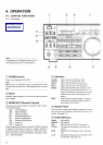
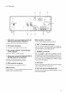
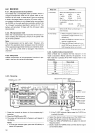
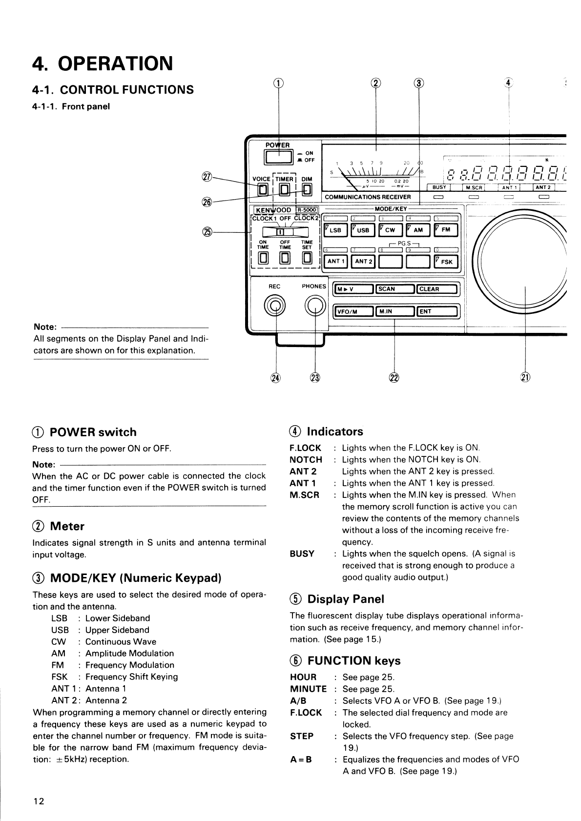
4-1-1. Front panel
Note:
All segments on the Display Panel and Indi-
cators are shown on for this explanation.
C)
POWER switch
Press to turn the power ON or OFF.
Note:
When the AC or DC power cable is connected the clock
and the timer function even if the POWER switch is turned
OFF.
® Meter
Indicates signal strength in S units and antenna terminal
input voltage.
®
MODE/KEY (Numeric Keypad)
These keys are used to select the desired mode of opera-
tion and the antenna.
LSB : Lower Sideband
USB : Upper Sideband
CW : Continuous Wave
AM : Amplitude Modulation
FM
: Frequency Modulation
FSK : Frequency Shift Keying
ANT
1:
Antenna 1
ANT 2 : Antenna 2
When programming a memory channel or directly entering
a frequency these keys are used as a numeric keypad to
enter the channel number or frequency. FM mode is suita-
ble for the narrow band FM (maximum frequency devia-
tion: ± 5kHz) reception.
® Indicators
F.LOCK : Lights when the F.LOCK key is ON.
NOTCH : Lights when the NOTCH key is ON.
ANT 2
Lights when the ANT 2 key is pressed.
ANT 1
: Lights when the ANT 1 key is pressed.
M.SCR : Lights when the M.IN key is pressed. When
the memory scroll function is active you can
review the contents of the memory channels
without a loss of the incoming receive fre-
quency.
BUSY : Lights when the squelch opens. (A signal
is
received that is strong enough to produce a
good quality audio output.)
®
Display Panel
The fluorescent display tube displays operational
informa-
tion
such as receive frequency, and memory channel
infor-
mation.
(See page 15.)
® FUNCTION keys
HOUR
: See page 25.
MINUTE : See page 25.
A/B
: Selects VFO A or VFO B. (See page 19.)
FLOCK : The selected dial frequency and mode are
locked.
STEP
: Selects the VFO frequency step. (See page
19.)
A = B
: Equalizes the frequencies and modes of VFO
A and VFO B. (See page 19.)
12
Scanned by Vincent
Downloaded by
RadioAmateur.EU