


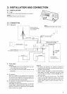
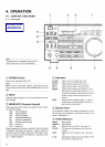
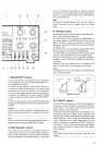
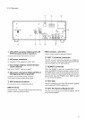
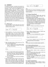
4-1-2. Rear panel
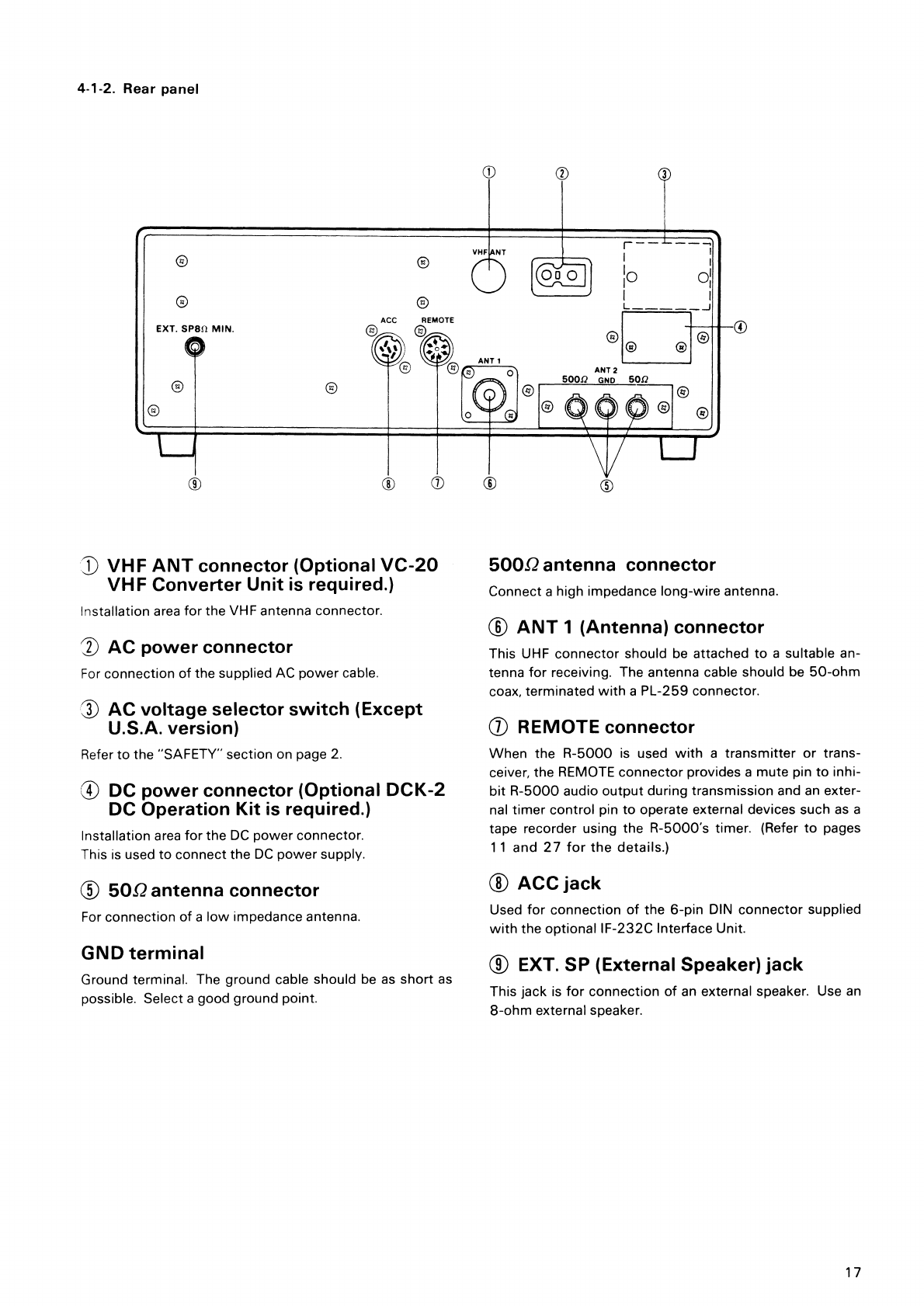
VHF ANT connector (Optional VC-20
VHF Converter Unit is required.)
Installation area for the VHF antenna connector.
AC power connector
For
connection of the supplied AC power cable.
1 AC voltage selector switch (Except
U.S.A. version)
Refer
to the "SAFETY" section on page 2.
4 DC power connector (Optional DCK-2
DC Operation Kit is required.)
Installation area for the DC power connector.
This is used to connect the DC power supply.
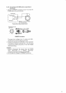
500 antenna connector
For connection of a low impedance antenna.
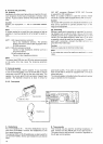
GND terminal
Ground terminal. The ground cable should be as short as
possible. Select a good ground point.
500 Ώ antenna connector
Connect a high impedance long-wire antenna.
®
ANT 1 (Antenna) connector
This UHF connector should be attached to a suitable an-
tenna for receiving. The antenna cable should be 50-ohm
coax, terminated with a PL-259 connector.
©
REMOTE connector
When the R-5000 is used with a transmitter or trans-
ceiver, the REMOTE connector provides a mute pin to inhi-
bit R-5000 audio output during transmission and an exter-
nal timer control pin to operate external devices such as a
tape recorder using the R-5000's timer. (Refer to pages
11 and 27 for the details.)
®
ACC jack
Used for connection of the 6-pin DIN connector supplied
with the optional IF-232C Interface Unit.
®
EXT. SP (External Speaker) jack
This jack is for connection of an external speaker. Use an
8-ohm external speaker.
17