


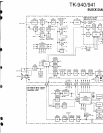
CIRCUIT DESCRIPTION
3-3.
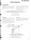
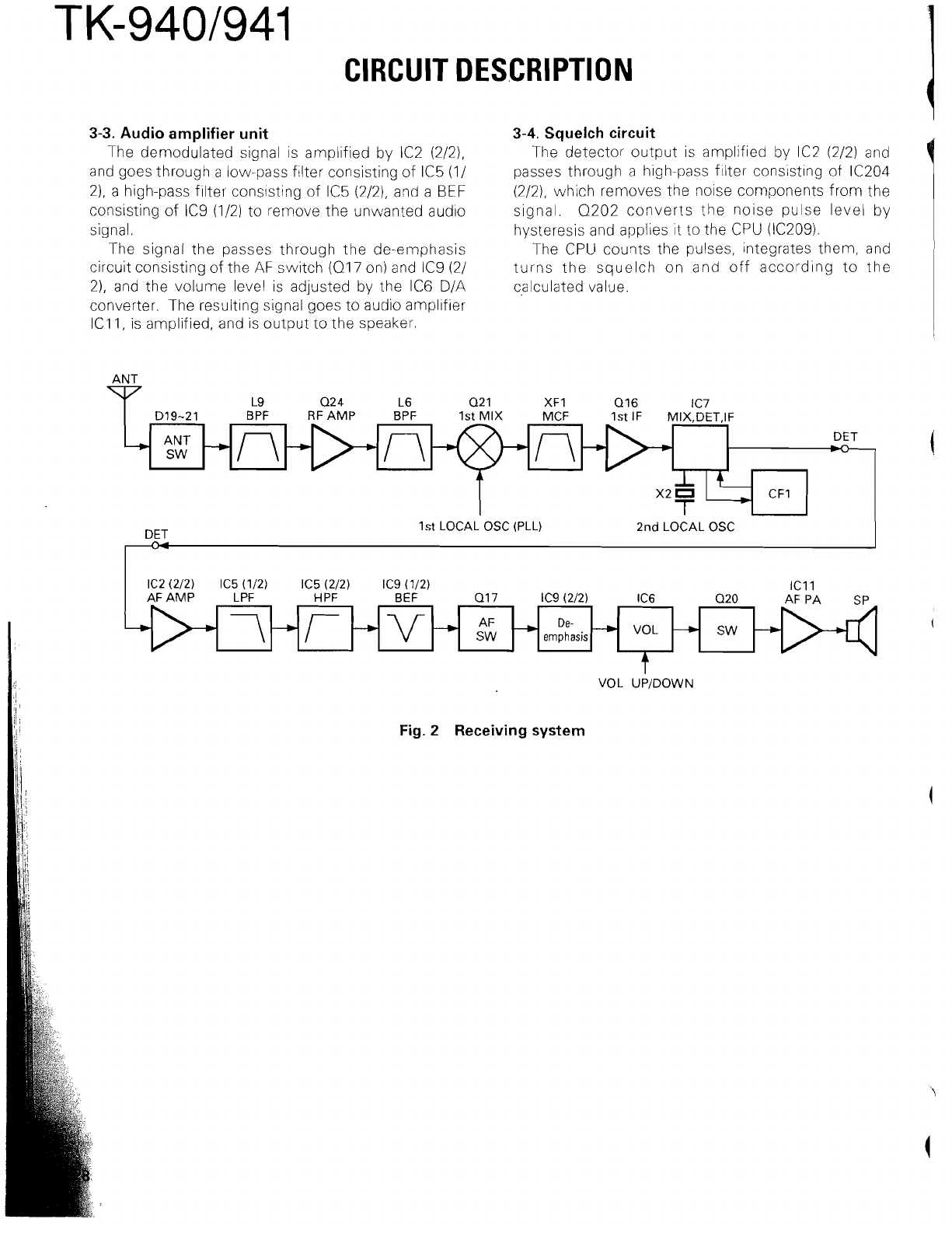
Audio amplifier unit
The demodulated signal is amplified by IC2 (2/2),
and goes through a low-pass filter consisting of IC5 (11
21, a high-pass filter cons~sting of IC5 (2/2), and a
BEF
consisting of IC9 (112) to remove the unwanted audio
signal.
The signal the passes through the de-emphasis
circuit consisting of the AF switch
(Q17 on) and IC9 (21
21, and the volume level is adjusted by the IC6 D/A
converter. The resulting signal goes to audio amplifier
IC11, is amplified, and is output to the speaker.
3-4.
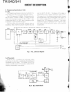
Squelch circuit
The detector output is amplified by IC2 (212) and
passes through a high-pass filter consisting of
IC204
(2/2), which removes the noise components from the
signal.
Q202 converts the noise pulse level by
hysteresis and applies it to the CPU
(lC209).
The CPU counts the pulses, integrates them, and
turns the squelch on and off according to the
calculated value.
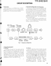
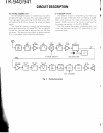
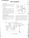
D19-21 BPF RF AMP BPF 1st MIX MCF 1st
IF
MIX;DET,IF
VOL UPIDOWN
Fig.
2
Receiving system
+
AF
AMP LPF
H
PF BEF 017 IC9 (212) IC6 020 AF PA SP
--+
DET
1 st LOCAL OSC (PLL)
2nd LOCAL OSC
z-n+>n
t
>
n
he
-"
DET
\-i
--V-
c
-)
De-
emphasis
-)
vOL
--,
SW
--+
(