1)
CIRCUIT DESCRIPTION
7.
LCD
Assembly
'
The LCD assembiy consists of CPU, LCD, power
switch circuit, and tone generator.
7-1. CPU
The CPU (IC2) carrres out the folowlng main
operatlons:
It sends onloff data serially to the control unit from
the AF volume control,
LIPIDOWN key, system
UP/
DOWN key, group UPIDOWN key, SCAlV key, and
AUX key. It receives serial data from the control unit
and displays it on the LCD.
The LCD can indicate alphanumeric characters
(13
segments,
8
d~gits), TX, BUSY, CALL, SCAN, Talk-
around, Option, AUX, TEL, and Delete.
7-2.
Power switch circuit
Each time the power key
IS
pressed,
a
pulse
IS
sent
to the TX-RX
unlt to turn the
transceiver
on or off.
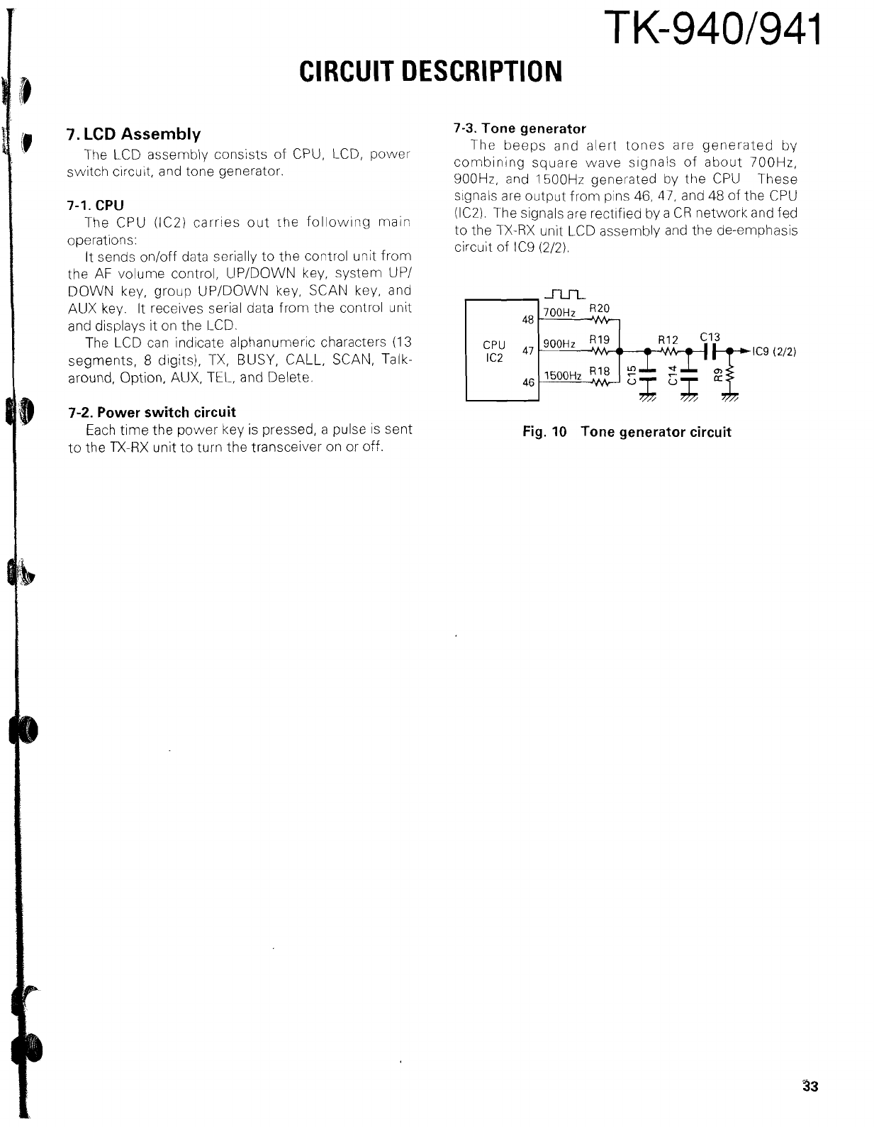
7-3. Tone generator
The beeps and alert tones are generated by
combining square wave
signals
of about 700Hz,
900Hz, and 1500Hz generated by the CPU These
signals are output from pins
46,
47, and
48
of the CPU
(IC2). The signals are
rectified
by a CR network and fed
to the TX-RX unit LCD assembly and the de-emphasis
circuit of
IC9 (212).
Fig. 10 Tone generator circuit


