


Figure 2-9 Rotating Plate Shipping Restraint Storage . . . . . . . . . . . .2-7
Figure 2-10 TracVision L2 Shipping Restraints (Storage Position) . . . .2-7
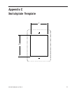
Figure 2-11 Switchplate Cutout Dimensions . . . . . . . . . . . . . . . . . . . .2-8
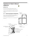
Figure 2-12 Antenna Baseplate Connectors . . . . . . . . . . . . . . . . . . . .2-8
Figure 2-13 Switchplate Connectors . . . . . . . . . . . . . . . . . . . . . . . . . .2-9
Figure 2-14 Installing Three or Four IRDs
Using an Active Multiswitch . . . . . . . . . . . . . . . . . . . . . .2-10
Figure 2-15 Installing the Clamshell Ventilator . . . . . . . . . . . . . . . . . .2-11
Figure 2-16 Switchplate Maintenance Port . . . . . . . . . . . . . . . . . . . . .2-15
Figure 2-17 PC Data Cable DB9 Connector . . . . . . . . . . . . . . . . . . . .2-15
Figure 2-18 Remote Dish Wiring Configuration . . . . . . . . . . . . . . . . .2-16
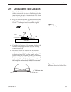
Figure 3-1 Be Aware of Objects that Might
Block the Satellite Signals . . . . . . . . . . . . . . . . . . . . . . . .3-1
Figure 3-2 Switchplate Front Panel . . . . . . . . . . . . . . . . . . . . . . . . . .3-2
Figure 4-1 Switchplate Maintenance Port . . . . . . . . . . . . . . . . . . . . .4-6
Figure 4-2 PC Data Cable DB9 Connector . . . . . . . . . . . . . . . . . . . .4-6
Figure 5-1 Antenna, PCB, and Rotating Plate . . . . . . . . . . . . . . . . . .5-3
Figure 5-2 Close-up of Connecting Rod and E-ring . . . . . . . . . . . . . .5-3
Figure 5-3 Antenna Assembly . . . . . . . . . . . . . . . . . . . . . . . . . . . . . .5-4
Figure 5-4 Rotating Plate . . . . . . . . . . . . . . . . . . . . . . . . . . . . . . . . .5-4
Figure 5-5 Removing the PCB Cover . . . . . . . . . . . . . . . . . . . . . . . . .5-5
Figure 5-6 PCB Connector Locations – Rear View . . . . . . . . . . . . . . .5-6
Figure 5-7 Attaching the Shipping Restraints
to the Antenna Baseplate . . . . . . . . . . . . . . . . . . . . . . . .5-10
Figure 5-8 Securing the Forward Shipping Restraint . . . . . . . . . . . .5-10
List of Tables
Table 1-1 TracVision L2 Packing List . . . . . . . . . . . . . . . . . . . . . . .1-2
Table 2-1 Installation Process . . . . . . . . . . . . . . . . . . . . . . . . . . . .2-1
Table 2-2 Kitpack Contents . . . . . . . . . . . . . . . . . . . . . . . . . . . . . .2-2
Table 2-3 TracVision L2 Operational Messages . . . . . . . . . . . . . .2-14
Table 2-4 DIRECTV On-screen Messages . . . . . . . . . . . . . . . . .2-14
iv