


2-9
Installation
54-0195 Rev. A
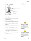
2.3.1 Connecting the Antenna to the
Switchplate
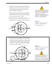
1. Connect one end of the antenna data/power cable
to the antenna’s data/power connector and lock in
place (see Figure 2-12).
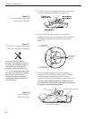
2. Route the other end of the data/power cable down
through the cable access hole in the vehicle’s roof
and out through the switchplate panel cutout.
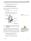
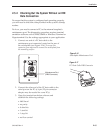
3. Connect the data/power cable to the switchplate’s
data/power connector and lock in place (see
Figure 2-13).
2.3.2 Connecting the Antenna to the IRD
1. Route an RF cable up through the roof’s cable
access hole.
2. Connect the RF cable to the antenna’s RF1
connector (see Figure 2-12). Once the cable is
securely connected, loosen the sealing nut at the
base of the RF1 connector and tighten it onto the
end of the RF cable.
3. Connect the other end of the RF cable to the IRD’s
SATELLITE IN connector.
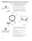
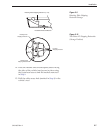
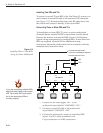
RJ11 Jack
(Data Cable to IRD - Optional)
Maintenance Port
(DB9 Connector)
Input Power
(+12 Vdc)
Ground
Switchplate Mounting
Hole (1 of 2)
Data/Power Connector
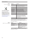
KVH recommends the use of
RG-6 or RG-11 (75 ohms) cable
for RF wiring. Use of non-RG-6
or RG-11 (75 ohms) cables will
result in degraded performance.
The KVH warranty does not cover
degraded performance due to
improper wiring.
Figure 2-13
Switchplate Connectors
When shipped from the factory, the
antenna’s RF connectors are
protected with caps. Leave the cap
installed on the RF2 connector
unless you are going to connect a
second RF cable to the
TracVision L2.