


5-6
A Guide to TracVision L2
7. Remove the 9 pan head screws securing the PCB
to the rotating plate.
8. Reverse this process to install the replacement
PCB. Reinstall all cable connectors removed in
Step 6.
9. Carry out the LNB calibration procedure
(Section 5.4.3).
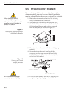
5.4.2 Antenna Gyro Assembly
Estimated Time to Repair: 1 hour
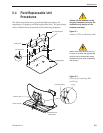
The antenna gyro assembly is mounted on the rear of the antenna
reflector bracket with four locking nuts and washers – Fig. 5-3.
Following the removal and replacement of the antenna gyro
assembly, it will be necessary to calibrate the gyro and restart the
system. Directions for removal, replacement, and calibration
follow:
1. Using needle-nose pliers, remove the E-ring from
one end of the connecting rod – Fig. 5-2.
2. Remove the connecting rod by sliding it off the
bracket.
3. Fully retract the elevation axis motor shaft
– Fig. 5-5.
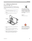
4. Remove 6 pan head screws from the PCB cover
flanges.
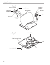
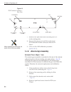
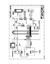
PCB
Limit Switches
Gyro
RF Connector
to IRD
RF Connector
to LNB
Elevation Motor Azimuth Motor
Cable Wrap
Fuse
J11
J2 J1
J4
Figure 5-6
PCB Connector Locations –
Rear View
When replacing the PCB cover, be
careful not to pinch any cables.