


5-7
Maintenance
54-0195 Rev. A
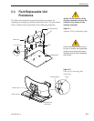
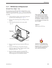
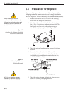
5. Remove the PCB cover. To get the necessary
clearance, rotate the linear actuator up 90º while
lifting the PCB cover – Fig. 5-5.
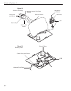
6. Remove the screw and clamp holding the cable to
the rotating plate; save the cable clamp for reuse –
Fig. 5-4.
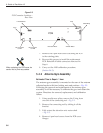
7. Remove the Molex connector from J11 on the CPU
board – Fig. 5-6.
8. Remove the 4 locking nuts and flat washers and
take the antenna gyro off the bracket.
9. Remove the antenna gyro gasket.
10. Replacement is the reverse of this procedure.
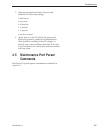
Antenna Gyro Calibration
1. Connect a PC to the communications port as
described in Section 4.4, “Computer Diagnostics.”
2. Type
HALT<cr> (<cr> indicates a carriage return/
ENTER key) while the system is performing the
limit switch initialization routine. The system will
complete the initialization function by finding the
azimuth and elevation switch limits and then go to
the home position.
3. Type
DEBUGON<cr> to enter Debug Mode.
4. Type
EL,300<cr>.
5. Type
=CALAZ<cr>. Verify that the Antenna Gyro
Azimuth scale factor is between -0.00090 and
-0.00110.
6. Type
=CALEL<cr>. Verify that the Antenna Gyro
Elevation scale factor is between 0.00090 and
0.00110.
7. Type
ZAP to restart/reinitialize the system.