


5-8
A Guide to TracVision L2
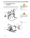
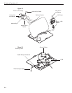
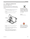
5.4.3 Antenna LNB Replacement
Estimated Time to Repair:
1
⁄2 hour
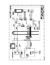
The LNB receives preamplifier operating power from the IRD via
the PCB – Fig. 5-3 and 5-4. Be certain that the IRD is disconnected
from its power source before removing or reconnecting the LNB.
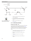
1. Disconnect both RF coaxial connectors at the LNB.
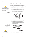
2. Remove the wing screw and washer from the LNB
clamp – Fig. 5-3.
3. Remove the top of the LNB clamp – Fig. 5-3.
4. Remove the LNB.
5. Replacement is the reverse of this procedure.
Check the rotation to ensure that the LNB is not
striking any wires or the baseplate.
Antenna LNB Normalization and Stability Test
1. Connect a PC to the maintenance port as described
in Section 4.4, “Computer Diagnostics.”
2. Ensure that the antenna is tracking the satellite.
3. Type
HALT<cr> (<cr> indicates a carriage return/
ENTER key) to put the system into Idle Mode.
4. Type
DEBUGON<cr> to put the system into
Debug Mode.
5. Type
FINDSAT<cr> to begin the automatic signal
peaking process. Wait until the antenna peaks the
satellite signal and is motionless. The screen will
display
FINDSAT: PASS.
6. Type =CALLNB<cr> to start the LNB
Normalization Function.
Note: The CALLNB Function requires the antenna
to be pointed directly at the satellite peak before
performing this routine.
7. The system must respond with the following
message:
CALLNB: PASS. If the system displays
CALLNB: FAIL, return to Step 3 and retry the
procedure, making sure to achieve the highest
possible RF signal peak.
8. Record the Cold Sky Average and the RFGAIN
value reported in Step 7.
The CALLNB Function requires the
antenna to be pointed directly at
the satellite peak before performing
this routine. Using the FINDSAT
command will ensure that the
antenna is receiving the strongest
possible signal.
When replacing the LNB, make
certain to restore it to its original
orientation, as shown in Figure 5-3.