


2-12
SECTION 2
INSTALLATION
VI. ELECTRICAL SUPPLY
WARNING
Authorized supplier personnel normally accomplish the
connections for the ventilation system, electric supply,
and gas supply, as arranged by the customer. Following
these connections, the factory-authorized installer can
perform the initial startup of the oven.
NOTE: The electric supply installation must satisfy the
requirements of the appropriate statutory authority, such
as the National Electrical Code (NEC), ANSI/NFPA70,
(U.S.A.); the Canadian Electrical Code, CSA C22.2; the
Australian Code AG601; or other applicable regulations.
NOTE: The electric supply connection must meet all
national and local electrical code requirements.
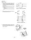
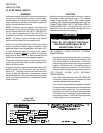
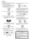
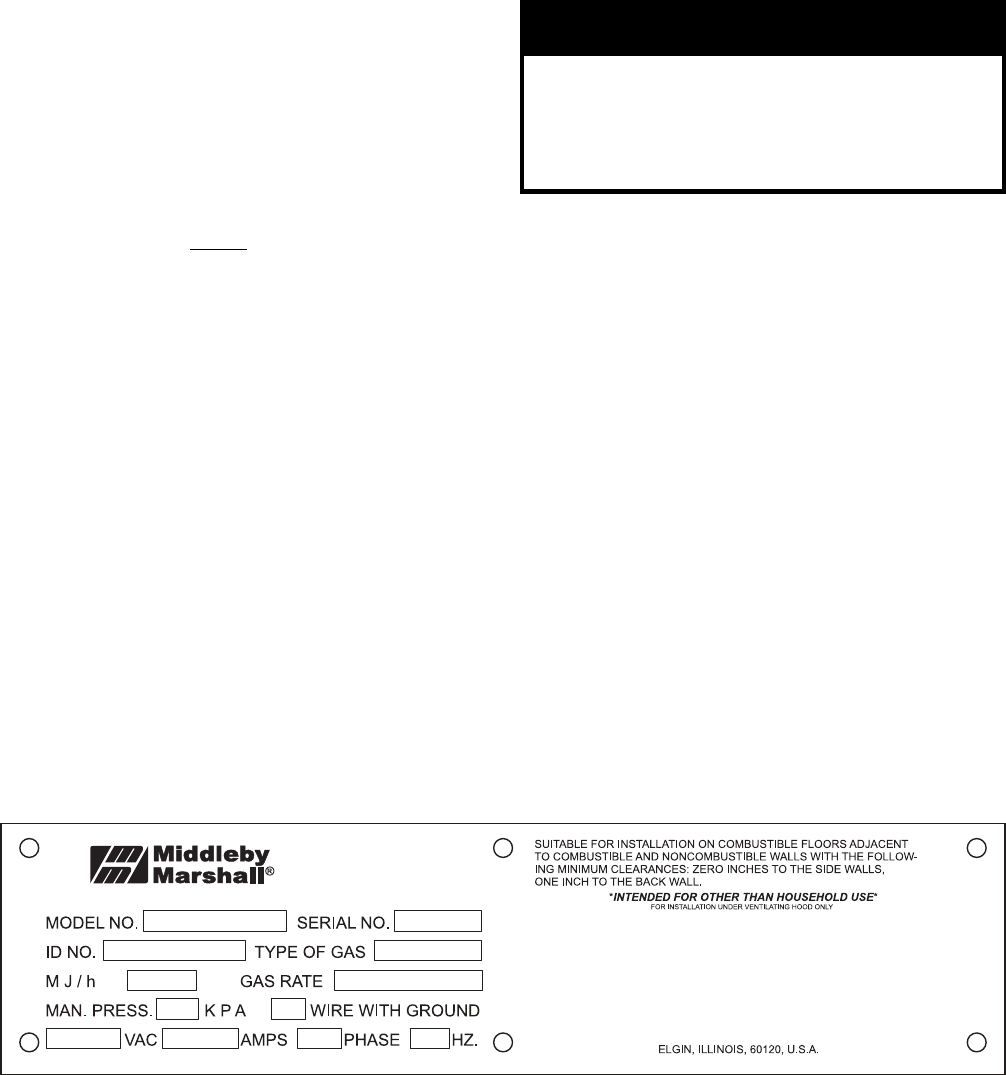
Check the oven data plate before making any electric
supply connections. Electric supply connections must
agree with data on the oven data plate. See Figure 2-26.
A fused disconnect switch or a main circuit breaker
(customer furnished) MUST be installed in the electric
supply line for each oven. It is recommended that this
switch/circuit breaker have lockout/tagout capability.
The supply conductors must be of the size (#14 AWG,
copper) recommended. Refer to the wiring diagrams in
Section 5 of this manual.
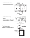
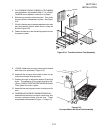
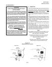
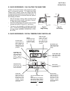
All gas oven electric supply connections are made via the
electrical junction box on the rear of the oven, shown in
Figure 2-27. The power lines then connect to the oven
circuits through the Machinery Compartment Access
Panel Safety Switch. This switch interrupts electric power
to the oven when the Machinery Compartment Access
Panel is opened.
CAUTION
Before connecting incoming power to the oven, measure
the voltage of each input leg to neutral. The expected
voltage is approximately 120V. ANY voltage reading
exceeding 130V indicates that the supply has a high leg.
CONNECTING A HIGH LEG TO THE OVEN VOIDS ALL
OVEN WARRANTIES. Connecting a high leg to the
black lead of the oven can severely damage the ovens
electrical and electronic components.
CAUTION
DO NOT CONNECT BLACK WIRE TO
HIGH LEG. VOLTAGE OF THE BLACK
AND WHITE WIRES MUST BE NO
HIGHER THAN 130 VAC
Figure 2-26
Oven Data Plate
FOR DOMESTIC OVENS (WITHOUT EXTERNAL
TRANSFORMERS):
In the junction box on the rear of the oven, connect one
208 - 240V supply line to the black wire and the other
208 - 240V supply line to the red wire. Connect the
electric supply ground wire to the oven ground screw
located in the junction box. If necessary, have the
electrician supply the ground wire. Do NOT use the
wiring conduit or other piping for ground connections!
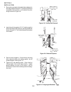
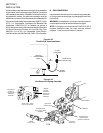
FOR EXPORT OVENS (WITH EXTERNAL
TRANSFORMERS):
First, position the transformer on the LEFT REAR wall
of the oven (as space permits), and fasten it in place
using the supplied mounting hardware.
Then, refer to the appropriate wiring diagram in Section
5 of this manual to determine the correct transformer
connections for the supply lines. Connect the electric
supply ground wire to the oven ground screw located
in the junction box. If necessary, have the electrician
supply the ground wire. Do NOT use the wiring conduit
or other piping for ground connections!