


4-3
SECTION 4
MAINTENANCE
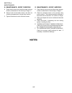
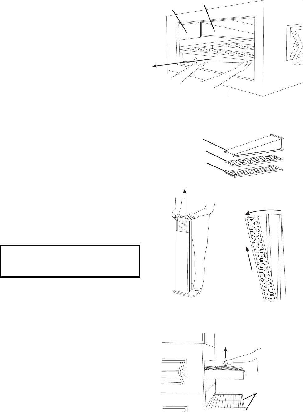
Lift here
Conveyor
adjustment
screws
(2 per conveyor)
II. MAINTENANCE - MONTHLY
A. Check that the oven is cool and the power is discon-
nected, as described in the warning on Page 4-1.
B. Remove the conveyor from the oven. (Pages 2-9 to
2-11 describe the installation of the conveyor; per-
forming this procedure in reverse allows the con-
veyor to be removed.)
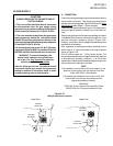
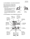
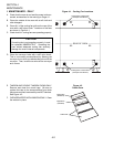
C. Slide the air fingers and blank plates out of the oven,
as shown in Figure 4-3. AS EACH FINGER OR
PLATE IS REMOVED, WRITE A "LOCATION
CODE" ON IT WITH A MARKER to make sure that
it can be reinstalled correctly.
Example of markings:
(Top Row) T1 T2 T3 T4 T5 T6
(Bottom Row) B1 B2 B3 B4 B5 B6
D. TRI TANDEM OVENS ONLY: To remove the air
fingers from the center section of the oven, the air
finger retaining screws must be removed. See
Figure 2-7 (Page 2-5).
E. QUAD TANDEM OVENS ONLY: To remove the air
fingers from the two center sections of the oven, the
transition must be disassembled. (Pages 2-7 to 2-8,
and Page 2-11, describe the assembly of the transi-
tion. Performing this procedure in reverse allows the
transition to be disassembled.)
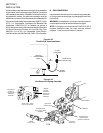
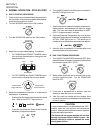
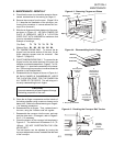
F. Disassemble the air fingers as shown in Figure 4-4.
AS EACH FINGER IS DISASSEMBLED, WRITE
THE "LOCATION CODE" FOR THE FINGER ON
ALL THREE OF ITS PIECES. This will help you in
correctly reassembling the air fingers.
Figure 4-3 - Removing Fingers and Plates
Figure 4-4 - Disassembling the Air Fingers
Figure 4-5 - Checking the Conveyor Belt Tension
Blank Plate
Air Finger
CAUTION
Incorrect reassembly of the air fingers will change
the baking properties of the oven.
G. Clean the air finger components and the interior of
the baking chamber using a vacuum cleaner and a
damp cloth. Refer to the boxed warnings on Page 4-
1 for cleaning precautions.
H. Reassemble the air fingers. Then, replace them in
the oven, using the "location code" as a guide.
I. Reassemble the conveyor into the oven, and reat-
tach the drive chain. Once again, refer to Pages 2-
9 to 2-11 if necessary.
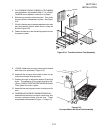
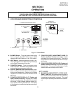
J. Check the tension of the conveyor belt as shown in
Figure 4-5. The belt should lift between 3-4" (75-
100mm). DO NOT OVERTIGHTEN THE CON-
VEYOR BELT.
The belt tension can be adjusted by turning the
conveyor adjustment screws, located at the idler end
of the conveyor.
1. Step on lip of manifold
2.
Pull outer plate
straight up
and off
3.
Swing ends of
inner plate and
manifold apart
4.
Pull inner plate
upwards, and
then away from
manifold
Manifold
Inner plate
Outer Plate