


English-18
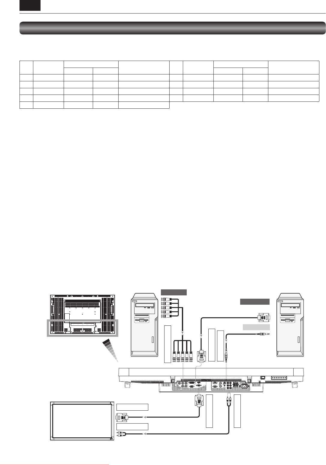
RGB cable
(Mini D-SUB 15-pin to
Mini D-SUB 15-pin)
To audio output
To BNC output
RGB4 IN (R,G,B,H,V)
BNC cable
(BNC x 5 to BNC x 5)
RGB3 IN (D-SUB)
RGB OUT (D-SUB)
AUDIO IN1 (mini)
AUDIO OUT (RCA)
Audio cable
(ø 3.5 mm stereo mini)
RGB3 IN (D-SUB)
AUDIO IN2 (RCA)
RGB cable
(Mini D-SUB 15-pin to
Mini D-SUB 15-pin)
RCA cable (audio)
To D-SUB output
R
B
G
HV
DVI IN
D-SUB IN
D-SUB OUT
HDMI
RS-232C IN
RS-232C OUT
VIDEO IN
VIDEO OUT
S-VIDEO
IN1
IN2
IN3
OUT
R
L
LCD monitor (rear)
LCD monitor (second monitor)
(Multi-connection)
Personal computer
(Analog RGB)
Personal computer
(Analog RGB)
LCD monitor (fi rst monitor)
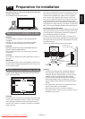
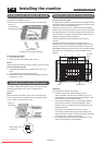
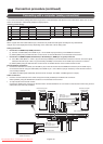
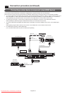
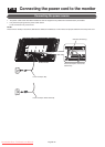
Connecting with a computer (analog connection)
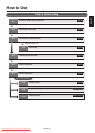
The monitor automatically distinguishes the timings shown in the table below and sets the screen information. When a PC or other
device is connected, it automatically displays images properly.
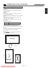
<Factory preset timing>
Resolution
Frequency
Remarks Resolution
Frequency
Remarks
Horizontal Vertical Horizontal Vertical
1 640 x 480 31.5 kHz 60 Hz 6 1280 x 1024 64.0 kHz 60 Hz
2 800 x 600 37.9 kHz 60 Hz 7 1600 x 1200 75.0 kHz 60 Hz
3 1024 x 768 48.4 kHz 60 Hz 8 1920 x 1080 67.5 kHz 60 Hz Recommend timing
4 1280 x 768 48.0 kHz 60 Hz 9 1920 x 1200 74.0 kHz 60 Hz
5 1360 x 768 47.7 kHz 60 Hz
NOTE:
When a signal other than 1920x1080 is input, characters may be blurred and fi gures and objects may be distorted.
Images may not be displayed correctly depending on the video card or driver being used.
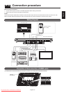
Analog connection:
• Connection via RGB3 IN (D-SUB) connector
(1) Connect an RGB cable (mini D-SUB 15-pin – mini D-SUB 15-pin) (accessory) to the RGB3 IN connector.
(2) Select [RGB3] using the INPUT button on the monitor or the D-SUB button on the wireless remote control.
• Connection via RGB4 IN (BNC: R•G•B•H•V, or R•G•B•Csync, RGB sync on green) connector
(1) Use a BNC cable (BNC x 5 - BNC x 5) (commercially available) to connect the BNC connector on the PC, and use a signal
cable (mini D-SUB 15-pin - BNC x 5) (commercially available) to connect the mini D-SUB 15-pin connector on the PC.
(2) Select [RGB4] using the INPUT button on the monitor or the BNC button on the wireless remote control.
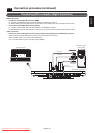
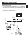
Second monitor connection:
• Connect the RGB OUT connector (mini D-SUB 15-pin) on the fi rst monitor and the RGB3 IN connector (mini D-SUB 15-pin)
on the second monitor using an RGB cable (mini D-SUB 15-pin - mini D-SUB 15-pin) (an accessory of the second monitor or
commercially available).
(The RGB3 or RGB4 signal selected by the fi rst monitor is output. The RGB1 or RGB2 signal isn’t output.)
Audio connection:
• Connect an audio cable (ø3.5 mm stereo mini) (commercially available) to the AUDIO IN1 connector.
Select [AUDIO1] using the AUDIO INPUT buttons on the wireless remote control.
• To output audio to the second monitor:
Connect the AUDIO OUT connector on the fi rst monitor and the AUDIO IN2 or 3 connector on the second monitor using an RCA
cable (audio) (commercially available).
P-4 Connection procedure (continued)
Downloaded From TV-Manual.com Manuals