


English-46
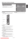
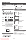
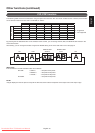
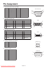
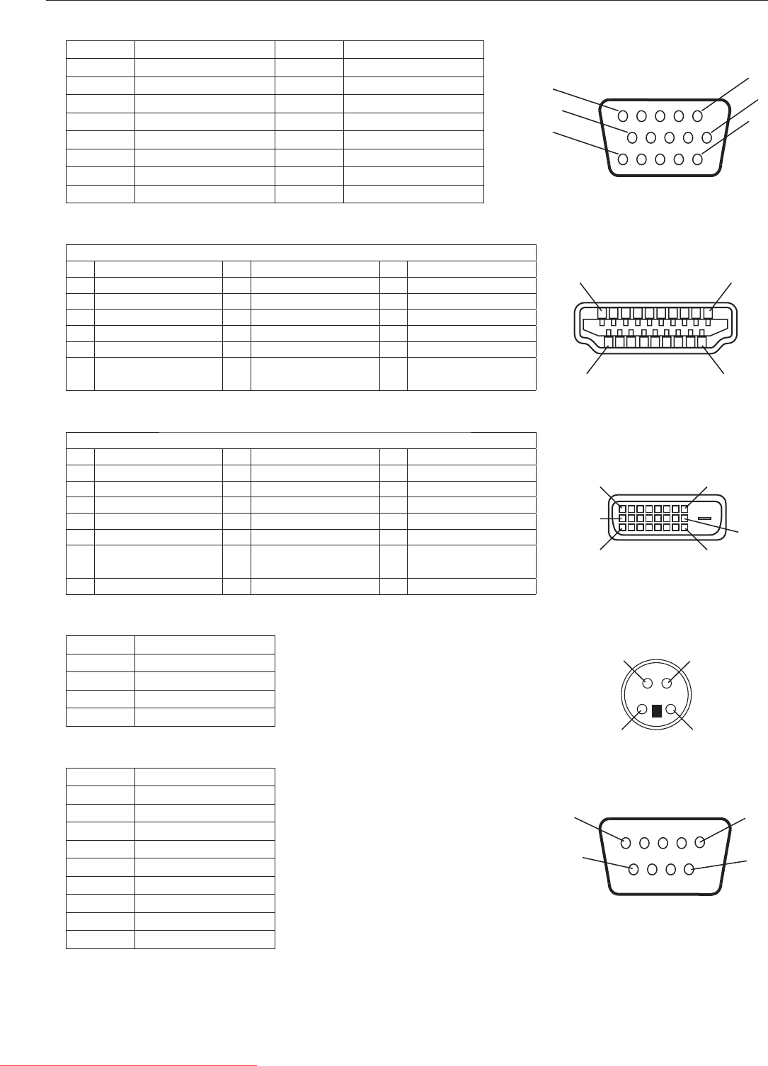
Mini D-SUB 15-pin
MINI DIN 4-pin
HDMI
DVI-D
D-SUB 9-pin
11
6
5
1
10
15
3
1
4
2
1
9
16
8
17
24
18
1
19
2
9
1
5
6
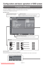
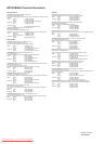
Pin Assignment
1) Analog RGB input (Mini D-SUB 15-pin): RGB3
Pin No Name Pin No Name
1 Video Signal Red 9 +5V (DDC)
2 Video Signal Green 10 SYNC-GND
3 Video Signal Blue 11 GND
4GND 12DDC-SDA
5DDC-GND 13H-SYNC
6Red-GND 14V-SYNC
7Green-GND 15DDC-SCL
8Blue-GND
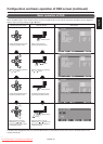
2) Digital RGB input (HDMI): RGB1
Pin - Assignment of
HDMI
connector:
1 TMDS Data2+ 8 TMDS Data0 Shield 15 SCL
2 TMDS Data2 Shield 9 TMDS Data0- 16 SDA
3 TMDS Data2- 10 TMDS Clock+ 17 DDC/CEC Ground
4 TMDS Data1+ 11 TMDS Clock Shield 18 +5V Power
5 TMDS Data1 Shield 12 TMDS Clock- 19 Hot Plug Detect
6 TMDS Data1- 13 CEC
7TMDS Data0+ 14
Reserved (N.C. on
device)
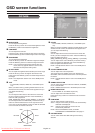
3) Digital RGB input (DVI-D): RGB2
Pin - Assignment of
DVI-D
connector:
1 TMDS Data2- 9 TMDS Data1- 17 TMDS Data0-
2 TMDS Data2+ 10 TMDS Data1+ 18 TMDS Data0+
3 TMDS Data2 Shield 11 TMDS Data1 Shield 19 TMDS Data0 Shield
4NC 12NC 20NC
5NC 13NC 21NC
6 DDC Clock 14 +5V Power 22 TMDS Clock Shield
7DDC Data 15
Ground (return for +5V,
H-SYNC and V-SYNC)
23 TMDS Clock+
8 Analog Vertical Sync 16 Hot Plug Detect 24 TMDS Clock-
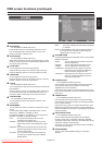
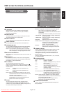
4) S-VIDEO input (MINI DIN 4-pin): VIDEO<S>
Pin No Name
1GND
2GND
3Y (Luminance)
4C (Chroma)
5) RS-232C input/output
Pin No Name
1NC
2RXD
3TXD
4NC
5GND
6NC
7NC
8NC
9NC
Downloaded From TV-Manual.com Manuals