


English
English-13
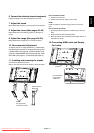
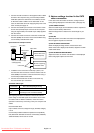
1. Connect the USB connector of the supplied CAT5 Tx BOX
and that of the computer using a commercially available
USB cable. (When the USB driver isn’t available, connect
an RS-232C cable in addition to the USB cable. In this
case, the USB cable serves for supplying the power to the
CAT5 Tx BOX.) See page 35.
2. Connect the D-SUB input connector of the CAT5 Tx BOX
and the VGA (D-SUB) output connector of the computer
using the signal cable (mini D-SUB 15-pin cable) supplied
with the monitor.
3. Connect the modular connector of the CAT5 Tx BOX and
the CAT5 (RGB5) IN connector of the CAT5 Rx BOX using
a commercially available CAT5 cable.
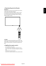
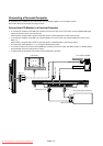
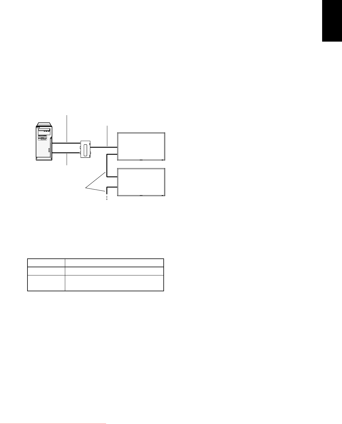
2) Connection to multiple monitors
1. In addition to the connection made step 1) above, con-
nect the CAT5 OUT connector of the fi rst monitor and the
CAT5 (RGB5) IN connector of the second monitor using a
commercially available CAT5 cable.
2. Connect the third and later monitors in the same way.
You can connect up to 5 monitors.
Allowable cable length
Connection Max. cable length/signal timing
One monitor 150 m / 1920 x 1080 @60 Hz
Multiple moni-
tors
200 m / 1920 x 1080 @60 Hz
(Total length of the connected cables)
The lengths given above are based on the actual measure-
ments using our standard signal source and the recommend-
ed cable as follows. Before installation, check the monitor
operation in advance by connecting it with your computer and
cables.
Recommended cable:
8-pin modular connector, straight-through, shielded, Category
5 or 5e
Commercially available cables that passed the compatibility
test (Tested with shielded connectors commercially available.):
7929A of Belden, NFTP-C5e-GY of Nex1
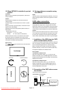
3. Various settings involved in the CAT5
video connection
In the case of the CAT5 video connection, confi gure the fol-
lowing settings displayed on the OSD screen. (See page 29.)
1) CAT5 CABLE LENGTH
Select the cable length, and the defaults of all the adjustment
values are automatically determined.
Select the length that is closest to the actual length of your
cable.
2) CAT5 EQ
Make adjustment so that blur and smear of the displayed let-
ters and graphic objects are minimized.
3) CAT5 R-GAIN/G-GAIN/B-GAIN
When the displayed image is dark, increase each value.
When whites aren’t displayed as intended, adjust the R-GAIN
and B-GAIN values.
4) CAT5 R-SKEW/G-SKEW/B-SKEW
Adjust each value so that the color deviation in the displayed
letters and graphic objects is minimized.
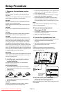
Computer
VGA (mini D-SUB 15-pin)
cable (supplied)
CAT5 cable
Monitor with CAT5
Rx BOX (option)
Monitor supporting
Mitsubishi CAT5
CAT5 Tx BOX
(option)
USB cable
CAT5 cable
Downloaded From TV-Manual.com Manuals