English
English-7
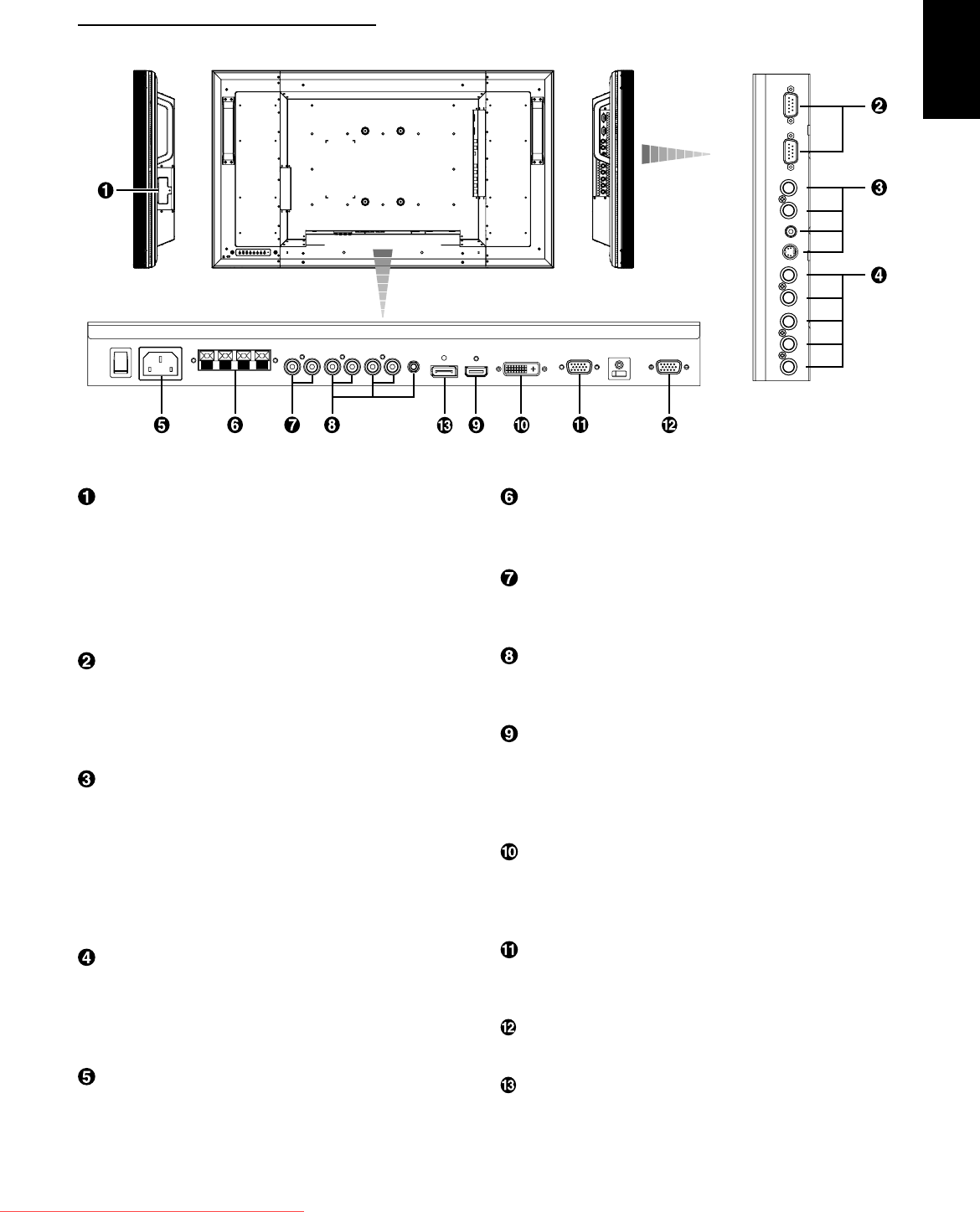
EXTERNAL SPEAKER TERMINAL
To output the audio signal for external speakers from AUDIO 1,
2, 3 jack or HDMI.
AUDIO OUT
To output the audio signal from the AUDIO IN 1, 2, 3 jack or
HDMI.
AUDIO IN 1, 2, 3
To input the audio signal from external equipment such as a
computer, VCR or DVD player.
RGB 1 IN (HDMI)
To input the digital RGB signals from a computer, DVD player,
etc.
* This connector does not support analog input.
AUDIO is supported via HDMI.
RGB 2 IN (DVI-D)
To input the digital RGB signals from a computer.
* This connector does not support analog input.
AUDIO is supported via DVI-D.
RGB 3 IN (mini D-Sub 15 pin)
To input the analog RGB signals from a computer or other
RGB equipment.
RGB OUT (mini D-Sub 15 pin)
To output the signal from RGB 3, 4 or 5 IN.
RGB 6 IN (DISPLAY PORT)
To input the digital RGB signals from a computer.
CAT5 Rx BOX slot
The CAT5 Rx BOX (option) is inserted in this slot. (See page
12.)
NOTE:
Never connect network devices to the CAT5 IN and OUT
connectors. If you do so, they may adversely affect with each
other, causing breakdown.
EXTERNAL CONTROL (mini D-Sub 9 pin)
Connect the IN connector with the RS-232C OUT connector
of the computer or a multi-connected MDT421S monitor.
Connect the OUT connector with the RS-232C IN connector
of a multi-connected MDT421S or MDT521S monitor.
VIDEO IN/OUT
VIDEO IN connector (BNC and RCA): To input a composite
video signal. BNC and RCA are not available at the same
time. (Use only one input).
VIDEO OUT connector (BNC): To output the composite
video signal from VIDEO IN connector.
S-VIDEO IN connector (MINI DIN 4 pin): To input the
S-video (Y/C separate signal).
RGB 4 IN / DVD/HD IN (BNC)
To input the analog RGB signals from a computer or other
RGB equipment.
Connecting equipment such as a DVD player, HDTV device,
or Laser disc player. See page 16, 18.
AC IN connector
Connects with the supplied power cord.
Connectors and Terminals
(OUT)
(IN)
(OUT)
(IN)
(IN)
(IN)
Downloaded From TV-Manual.com Manuals


