24 C2988M-A (6/11)
OSD MENU FOR VIDEO WALL SETUP
1. Press Menu on the remote control or control panel.
2. Press Up or Down to navigate to the Advanced Settings screen.
3. Press Right to enter the Advanced Settings menu.
4. Press Up or Down to navigate to the Video Wall submenu.
5. Press Right to access the Video Wall settings menu; the default setting is No.
6. Navigate to the Video Wall option, and press Right to change the Video Wall setting from No to Yes. The video wall menu displays.
7. Configure the video wall. Refer to Video Wall Parameters on page 20 for more information.
8. Press Menu on the remote control or control panel to exit.
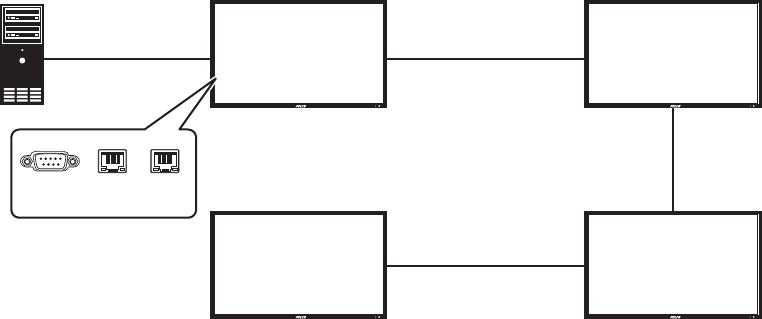
RS-232 CONTROL
Connect an RS-232 terminal or a personal computer to the video wall using an RS-232 cable (not supplied) from the controlling device to the first
monitor. Use three RS-485 cables (not supplied) to connect the remaining three monitors.
Figure 14. RS-232 Connection
NOTES:
• To function correctly, any monitors using an RS-485 OUT connection can only be connected to another monitor of the same series model.
• RS-232 connections only support 9-pin serial straight cables; crossover or null modem cables are not supported.
• RS-485 connections only support Cat5 straight cables; crossover cables are not supported.
For more information on creating a video wall, contact Pelco Product Support at 1-800-289-9100 (USA and Canada) or +1-559-292-1981
(international) for assistance. Be sure to have the serial number available when calling.
(1,1) (2,1)
(1,2) (2,2)
RS-485 IN RS-485 OUT
RS-485 OUT RS-485 IN
RS-232 IN
RS-485 OUT
RS-485 IN
RS-232 RS-485
IN
RS-485
OUT


