


11
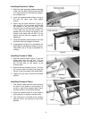
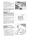
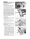
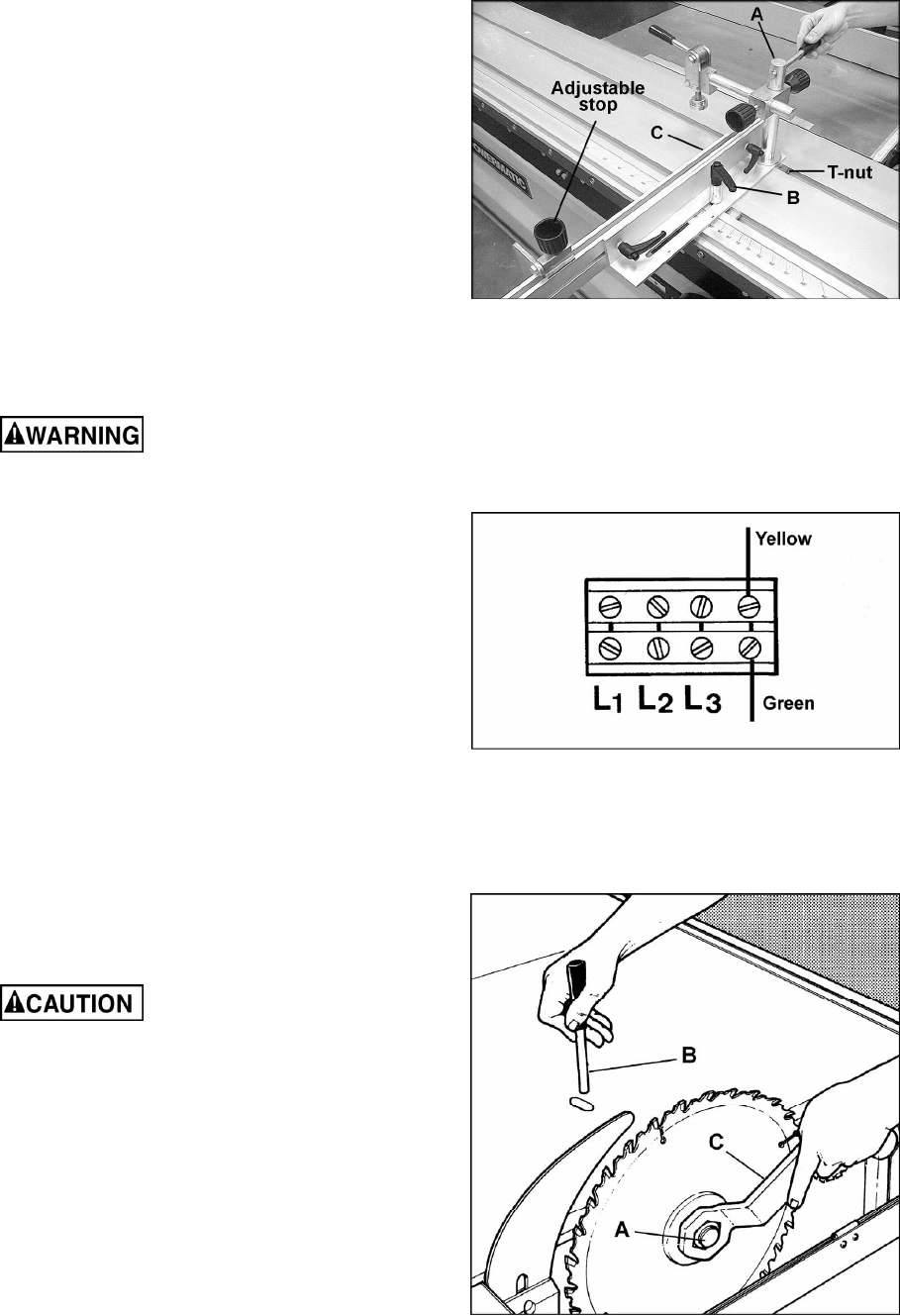
Installing Miter Fence
Mount the miter fence assembly as shown in
Figure 13. Tighten the rod (A, Figure 13) with
the provided pin into the stationary T-nut.
NOTE: Do not move the stationary T-nut; it has
been calibrated with the angle scale.
Screw the large lock lever (B, Figure 13) down
into the other T-nut.
Loosen the small lock levers and slide the
aluminum fence (C, Figure 13) on to the
assembly as shown. The adjustable stop can be
mounted to the fence if desired for making
multiple cuts of the same length.
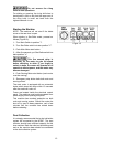
Electrical Connections
Electrical connections must
be performed by a qualified electrican. The
machine must be properly grounded to help
prevent electrical shock and possible death.
Check that the voltage of the machine
corresponds with the voltage of your power
supply.
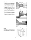
Remove the electrical box cover and introduce
the cable. Connect the three wires to the
terminals L1, L2, L3 (Figure 14).
The green ground wire must be connected to
the yellow wire terminal.
Turn on the main saw motor [see "Starting the
Machine"] and check that the blade arbor
rotates clockwise (as viewed from front of
machine). If it does not, turn motor off,
disconnect from power source, and exchange
wires L1 and L2.
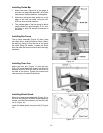
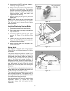
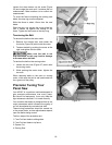
Installing/Replacing Main Blade
Use care when working
around sharp blades. Use only carbide
tipped saw blades, not High Speed Steel
blades.
1. Disconnect machine from power source.
2. Push sliding table all the way to the left, and
open blade cover.
3. Raise main saw blade to its highest position
and place spanner (C, Figure 15) over the
arbor nut (A, Figure 15).
4. Insert the locking pin (B, Figure 15) into the
hole on the saw table and turn the arbor
with the spanner until the locking pin
engages the hole in the saw arbor pulley.
Figure 13
Figure 14
Figure 15