


15
When bevel cutting, make
sure the appropriate blade guard has been
mounted before operating the saw.
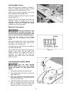
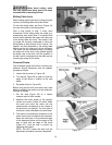
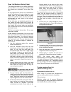
Sliding Table Lock
When loading panels and when cutting using the
rip fence, the sliding table should be locked.
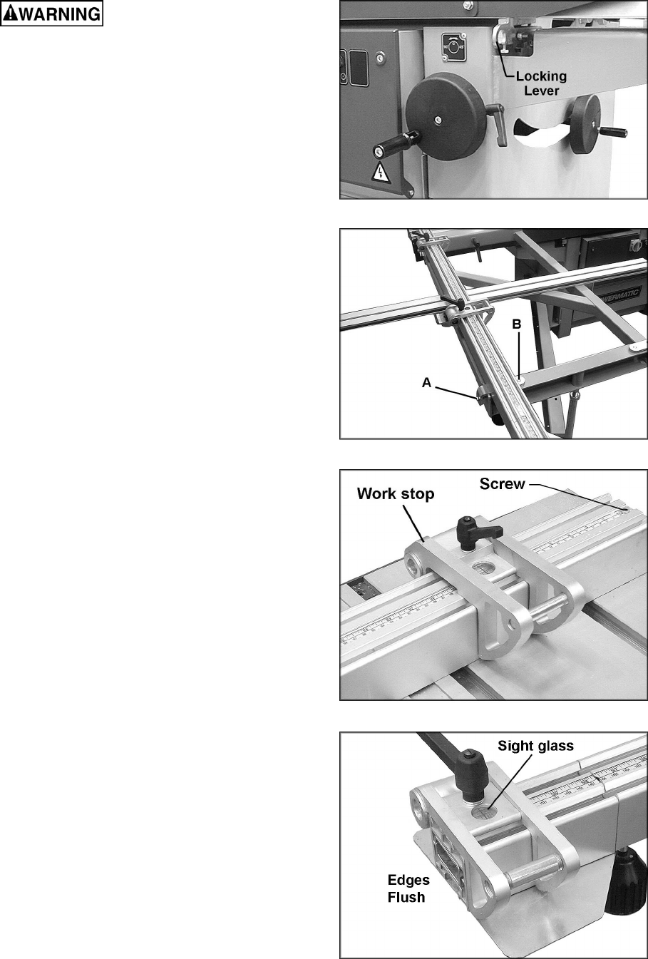
To lock the sliding table, pull lever (Figure 24)
into one of the slots in the sliding table.
Over a long period of time, if many short
movements of the sliding table are made (e.g.
crosscutting solid wood) then it is possible that
the ball carrier between the upper and lower part
of the sliding table will move. This means it will
no longer be correctly positioned to allow the
sliding table to slide through its full course. The
operator will feel resistance in the sliding table
motion and the full stroke will not be achieved.
This effect can be corrected simply by pushing
the table with a few short, light pushes against
the buffer stop at the end, until the position of
the ball carrier is adjusted and the table can be
moved again along its full stroke.
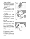
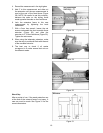
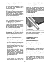
Crosscut Fence
The 90-degree angle of the fence is factory set.
However, should adjustment ever be needed,
proceed as follows:
1. Loosen the two bolts (A, Figure 25).
2. Turn bolt (B, Figure 25) to open or close the
angle of the fence in relation to the saw
blade.
3. Re-tighten bolts (A, Figure 25).
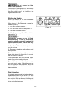
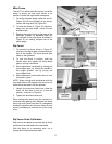
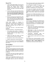
Before using the first time, and each time a new
blade is installed, the scales must be calibrated.
Proceed as follows:
1. Put the stop (Figure 26) at a certain
measure and cut off a sample.
2. Measure the exact length of the sample.
Loosen the screw (Figure 26) which holds
the scale and move the scale until the
measurement corresponds to the length of
the previously cut sample. The main part of
the fence is now calibrated to the saw blade.
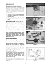
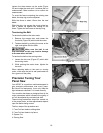
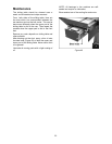
3. The scale on the telescopic extension of the
fence should now be checked and adjusted.
Move the other stop to the outermost edge
of the extension fence until the edge of the
stop is flush with the edge of the fence
(Figure 27). Lock the stop in position by
tightening the handle.
NOTE: DO NOT loosen the stop until the
adjustment procedure has been completed.
Figure 24
Figure 25
Figure 26
Figure 27